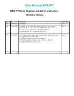
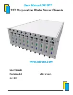


User Manual B410PT
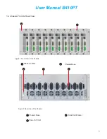
Front View of the Chassis ................... ....................................................................3
Rear View of the Chassis ........................................................................................3
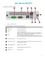
Front Panel indicator ..............................................................................................4
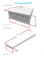
Chassis Dimension .................................................................................................5
Blade Dimension .................................................................................................5
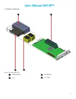
Blade Opened view ..............................................................................................6
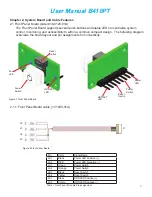
Front Panel Board ................................................................................................7
Front Panel IO cable (to server board) ...............................................................7
Serial ATA Backplane board ................................................................................. 8
22-pin Serial ATA connector ...............................................................................8
7-pin Serial ATA connector ...................................................................................9
7-pin Serial ATA point-to-point cable ....................................................................9
4-pin Power Header .........................................................................................9
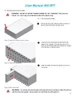
Indentify the blade unit you want to remove .......................................................11
Loosen the thumb screws ....................................................................................11
Slide out the blade ................................................................................................11
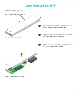
Remove the blade rear cover ............................................................................. 12
Remove the blade front cover ..............................................................................12
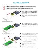
Remove the copper standoff .................................................................................13
Install the Port Townsend board ...........................................................................13
Secure the board by tighten mounting screws .................................................13
Insert the HDD into the mounting bracket .....................................................14
Secure the HDD on the mounting bracket ............................................................14
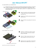
Remove the fan from the blade ........................................................................15
Change to the new fans ....................................................................................15
Change the exhaust fan ......................................................................................15
Take out the PSU mounting screws ......................................................................16
Replace the Power Supply Unit .........................................................................16
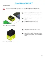
Replacing the system battery ....................................................................... 17
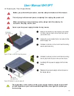
Install the stand-alone top cover ...........................................................................18
Install the stand-alone bottom cover ......................................................................18
Install the stand-alone wheel bracket ..................................................................18
Four post rack ........................................................................................................21
Four post open rack ................................................................................................21
Rack’s mounting hole types .................................................................................21
Marking on the rack ..............................................................................................22
Removing the L-shape rack mounting bracket .......................................................23
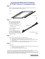
Install the L-shape rack mounting bracket ............................................................23
Install the chassis into the rack ..........................................................................23
CPU fan and P-V curve .......................................................................................24
Exhaust fan and P-V curve......................................................................................25
275W Power Supply Unit ......................................................................................25
Figure 1
Figure 2
Figure 3
Figure 4
Figure 5
Figure 6
Figure 7
Figure 8
Figure 9
Figure 10
Figure 11
Figure 12
Figure 13
Figure 14
Figure 15
Figure 16
Figure 17
Figure 18
Figure 19
Figure 20
Figure 21
Figure 22
Figure 23
Figure 24
Figure 25
Figure 26
Figure 27
Figure 28
Figure 29
Figure 30
Figure 31
Figure 32
Figure 33
Figure 34
Figure 35
Figure 36
Figure 37
Figure 38
Figure 39
Figure 40
Figure 41
Figure 42
List Of Figure