18
(4) Motor
■
General precautions
1. Perform the wiring work according to the electric equipment technical standard and the regulations of
the electric power company. Take care that the voltage drop is not large, since the longer the wiring
distance becomes, the more the voltage drop will increase. Generally, you should use electric wire that
has proper thickness and length that will not cause the voltage to drop 2% or more. Voltage drop may
prevent brake release. Use a power supply which is described on the nameplate.
2. Refer to the Table 2 below for the applicable cable diameter. Using cables with smaller diameter will
render the waterproof feature ineffective.
3. After wiring is completed, check the mounting set screws and connector whether they are not loose.
4.
Grounding
After installation of the Linipower Jack, ground the motor (Earth work in class 3 or higher).
Table 2. (Motor terminal box)
Motor capacity
Connector
configuration
Applicable cable
diameter
Connector
mounting part
Size of ground
terminal
0.2 to 0.4 kW
SK-14L
φ
11 to
φ
13
G1 / 2
M4
0.75 to 1.5 kW
A20c
φ
14 to
φ
15
G3 /4
M4
2.2 to 2.3 kW
A25c
φ
19 to
φ
20
G1
M4
※
Connector connection will be required depending on lead-out part size of the terminal box or when servo
motor is used. Please refer to the drawing when using a special type motor.
∎
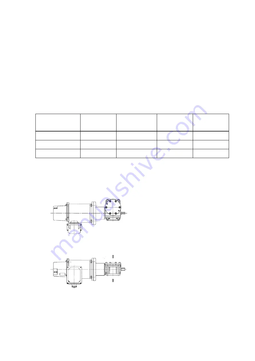
Motor connection
The screw shaft of the standard type and rotation
prevention type move in the direction of the
arrows shown in the picture on the left with
normal wiring. The traveling nut moves in the
same direction as the travel screw.
Note: Add necessary protective devices to each
contact site.
Note: Please comply with the regulations of
electric companies for switches and fuse.
★
★


