29
( 2 ) Jack with 0.1kW to 1.5kW Gear Motor
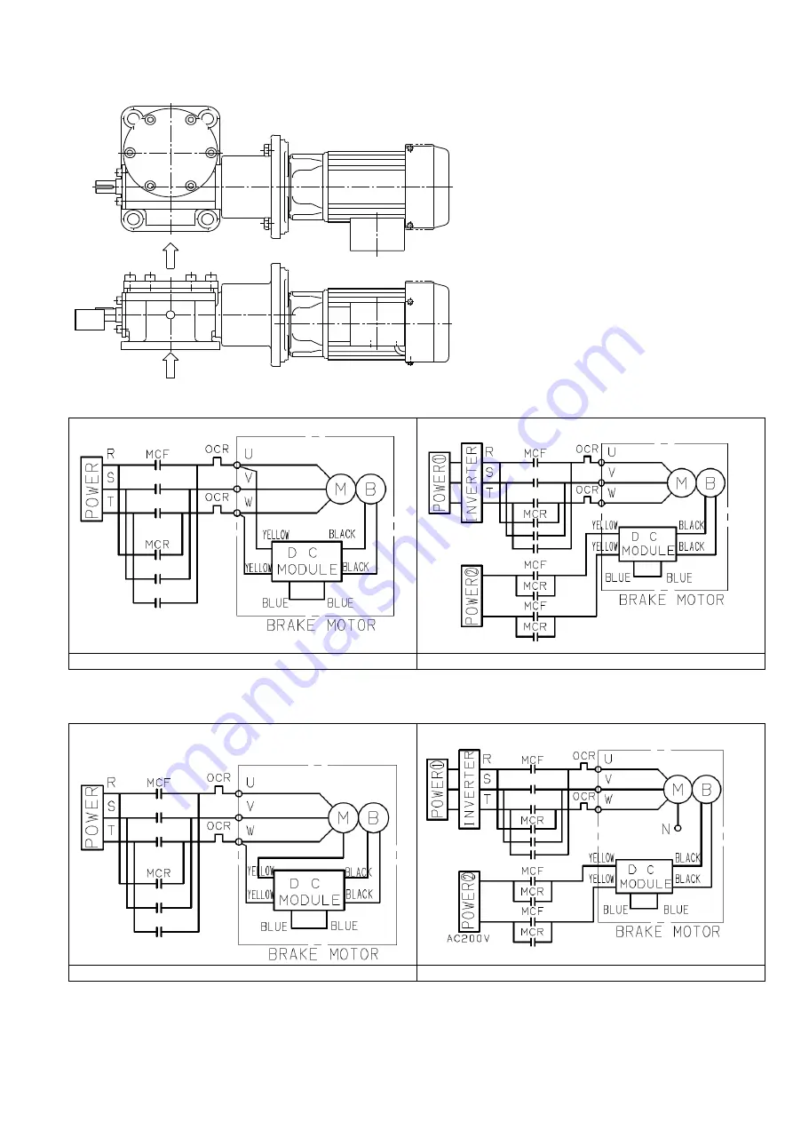
200V class connection diagram
AC Simultaneous Cut
AC Separate Cut (when using an inverter)
400V class Connection diagram
AC Simultaneous Cut
AC Separate Cut (when using an inverter)
Note:
When you use separate brake power supply operation using 400V class power source, please insulate by cutting wiring at N which is
wired with closed end terminal. In this case, you have to input 200V power to the DC module.
※
In case of made-to-order product, please confirm the final drawing, the connection might not be same.
The travel screw of the standard jack and keyed
machine screw jack moves in the direction of the
arrow shown in the picture to the left picture and
wired as shown below. The traveling nut moves in
the same direction as the travel screw.
If two of the wires among white, gray and black
are changed, the travel screw will move in the
reverse direction.
1) Use a rated load of AC250V, 7A and
larger for the electro-magnetic switch of
the 200V class brake.
2) The DC Module has a surge absorption
protective device.
3) Add necessary protective devices to each
contact site.


