6
Frame No.
Amount of grease
Initial enclosed quantity
screw shaft
(
amount per 100mm stroke
)
Reducer unit
002
5 g
35 g
005
5 g
35 g
010
5 g
80 g
025
10
–
15 g
170 g
050
10
–
15 g
370 g
100
20
–
30 g
470 g
150
20
–
30 g
700 g
200
40
–
50 g
830 g
300
40
–
50 g
2600 g
500
50
–
100 g
5500 g
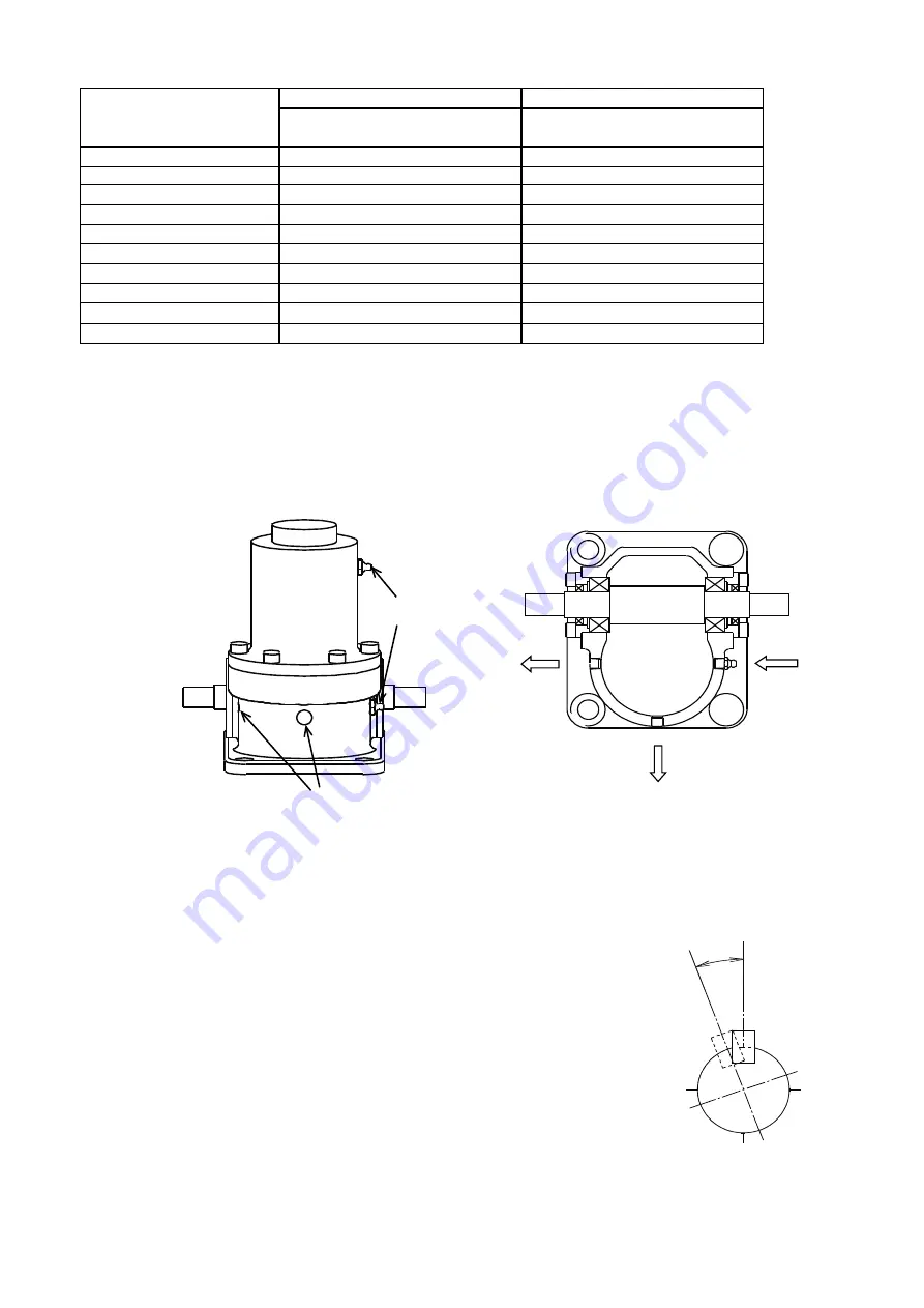
3 Reducer units JWM025/JWB025/JWH025 and above are provided with grease nipples and hex socket
plugs. Remove the plugs and pour grease through the nipples until it seeps from the openings. Then
firmly seal the openings with tape.
4
Grease upper bearings for JWB (Ball Screw Type) and JWH (High Lead Ball Screw Type) using the
grease nipple set attached to their housings, at 6-month intervals.
Not necessary for jacks JWB010/JWH010 and below.
※
In case of the made-to order type, confirm with the final drawing, grease nipple might not be same
as above.
4 Inspect regularly for general backlash and screw unit condition.
Jack life and replacement timing are determined by the following:
• JWM
--- Backlash in the direction of screw shaft and nut
hits 1/4 of the screw pitch.
• JWB/JWH
--- Visible particles due to wear and tear of the screw unit
• ALL types
--- Check for backlash between the worm and worm gear.
Backlash excess of 30
˚
for H speed and 60
˚
for L speed
indicates the need to replace the worm and worm gear.
(Angle C in Fig.6)
Generally, continuous use without lubrication at recommended
intervals may cause inefficiency of shaft and failure of travel nut.
Pouring grease
Grease
Grease
Grease nipple
Hex plug
Fig.4. Grease nipple
Fig. 5. Greasing method
Table 5. Amount of Grease
Fig.6. Input backlash
C
★


