MODEL
442A
TSURUGA ELECTRIC CORPORATION
8
4.1.1 Input/Output signals
DATA, STROBE
――――――
, INIT
___
: I
IL
≦
-1mA
、
"L"=0 to 1.5V
、
"H"=3.5 to 5V
ACK
___
, BUSY, ERR
___
, PE : TTL level (CMOS compatible), Fo=1
SD, RD : “L”= -5 to -15V. “H”= 5 to 15V
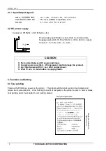
4.2 DC power supply
Connector: VHR-2N ( J.S.T. Mfg Co.,Ltd.
)
Power supply specification is described on terminal plate.
Supply power within 10.8 to 26.4V d.c. (12 to 24V d.c. rated)
C to + side, and – to – side.
CAUSION
No isolated between DC power and Input.
Supply power specified. Wrong power might damage the product.
Get rated power within 1 sec. after supply power.
Wait 10 sec. or more before re supply power.
5. Function and Setting
5.1 Test printing
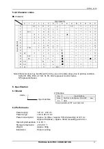
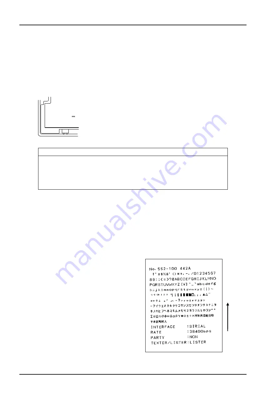
Pressing the FEED key, power on the printer. The printer will then start a print of test pattern and
makes an incremental print. After finishing the print of test pattern, the printer returns to normal status.
Test printing prints “test pattern” and “setting status”.
1.1 A
12V-24V
+ -
Test printing sample
P
aper
f
eed dir
e
c
tion

