MODEL
442A
TSURUGA ELECTRIC CORPORATION
7
4. Wiring
WARNNING
After turn Power Off, do wiring works. Otherwise, electric shock
might be assumed.
Don’t do wiring works with wet hands or under high humid
environment. Otherwise, electric shock might be assumed.
Do not touch power terminals while powered. Otherwise, electric
shock might be assumed.
CAUSION
Do correct wiring. Wrong wiring might be caused of product
damages.
Use specified power and load in specification. Wrong power and
load might be caused of product damage.
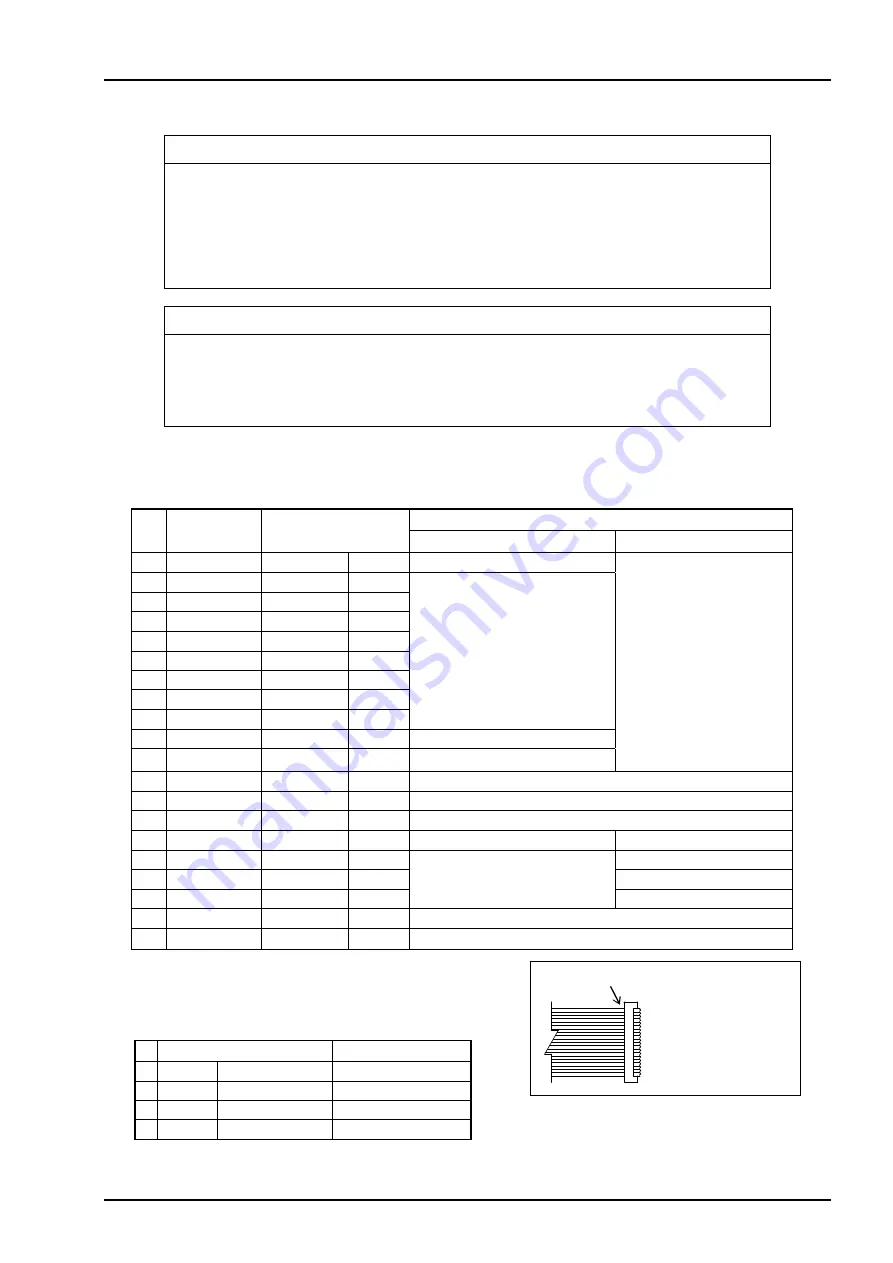
4.1 Connector arrangement
Connector: XG4A-2034(Omron)
Upper bar means Negative Logic.
Note) Do not connect at non use
442A-E2 (USB)
Connector USB 4P Type A
No.
Signal
Function
1 VBUS
No use
2 D -
Input, Output
USB data ( - )
3 D +
Input, Output
USB data ( + )
4 GND
Ground
Pin
No.
Cable Color
Signal
Function
Parallel (Centronics)
Serial (RS-232C)
1
Brown
STROBE
 ̄ ̄ ̄ ̄ ̄ ̄ ̄ ̄
Input
Data input
-
(Note)
2
Red
DATA 0
Input
JIS8 Bit code input
3
Orange
DATA 1
Input
4
Yellow
DATA 2
Input
5
Green
DATA 3
Input
6
Blue
DATA 4
Input
7
Purple
DATA 5
Input
8
Gray
DATA 6
Input
9
White
DATA 7
Input
10
Black ACK
 ̄ ̄ ̄ ̄
Output
Data input complete
11
Brown
BUSY
Output
Input data read error
12
Red
PE
Output
Paper end
13
Orange
ERR
 ̄ ̄ ̄ ̄
Output
Error
14
Yellow
INIT
 ̄ ̄ ̄ ̄
Input
Initializing (valid at Lo for 10ms
≦
)
15
Green
COM
Data common
-
16
Blue
SG
-
(Note)
Ground
17
Purple
SD
Output
Send
18
Gray
RD
Input
Receive
19
White
NC
No connection
20
Black
NC
No connection
△
mark (1 pin)
Attached cable
(Top view)

