Page 16
Maintenance
Tsurumi’s Operation, Service, and Repair Manual
A.
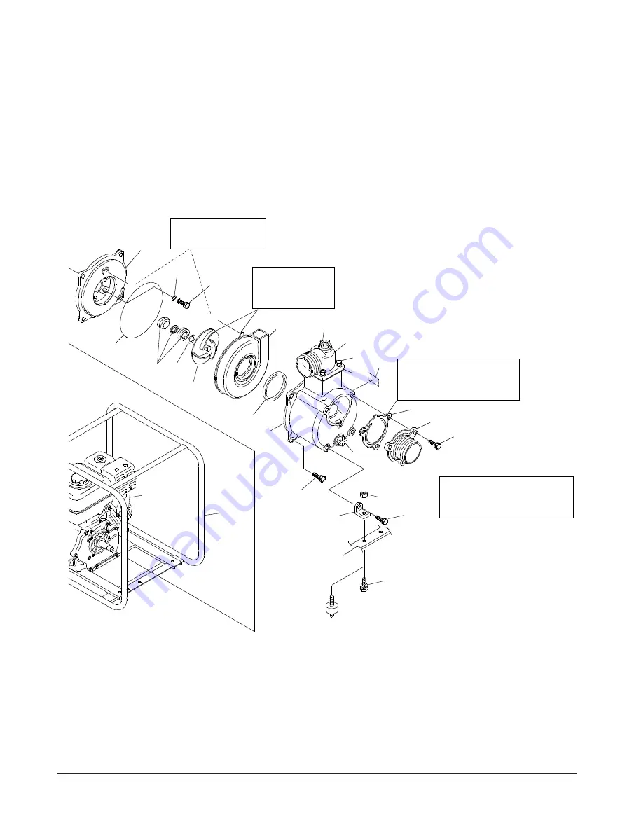
Remove Centrifugal Pump Components
(1)
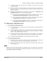
Remove two screws (30) from bracket (25) and pump casing (1). Remove two spring
nuts (27) and two brackets (25).
(2)
Position the frame (21) so the pump is facing up (with the engine shroud down).
(3)
Remove four bolts (18) and lift casing (1) from casing cover (2).
(4)
Remove volute casing (4), packing (9), and O-ring (8). Check packing (9) and O-ring
(8) for damage and replace if damaged.
(5) Using a hard plastic hammer, sharply rap on the end of the hex on impeller (3). If
impeller (3) did not come loose, put a wooden block against one of the impeller
vanes. Then strike the wooden block (counterclockwise) with a hammer to loosen the
impeller.
(6)
Rotate impeller (3) until it can be removed from the threaded end of the engine crank-
shaft.
2
17
14,15,16
9
7
31
3
A: PUT TAB ON (4)
IN POCKET OF (2)
A
MEASURE AND
CALCULATE
SHIM (31)
A
4
12,13
5
19
10
INSTALL CHECK VALVE
WITH FLAT SIDE OUT.
PUT TAB AT TOP.
1
18
11
6
20
12,13
27
30
25
FRAME
(REF. 21)
BOLT (TE
3
-100 HA)
33
21
8
NOTE: ITEM (27) IS ITEM
(26) ON TE
3
-100HA
34
CUSHION (TE
3
-50 HA/TE
3
-80 HA)
Figure 4-4: Removal of Internal Components


