AB Connectors Limited
Specification No. 528
ABCIRP Connector Series
Assembly and wiring Instructions
AB Connectors Limited Issue 9: July 2010
Page 10 of 41
4
Polarisation
4.1
Insert Orientation
4.1.1
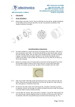
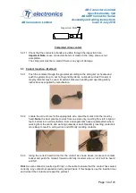
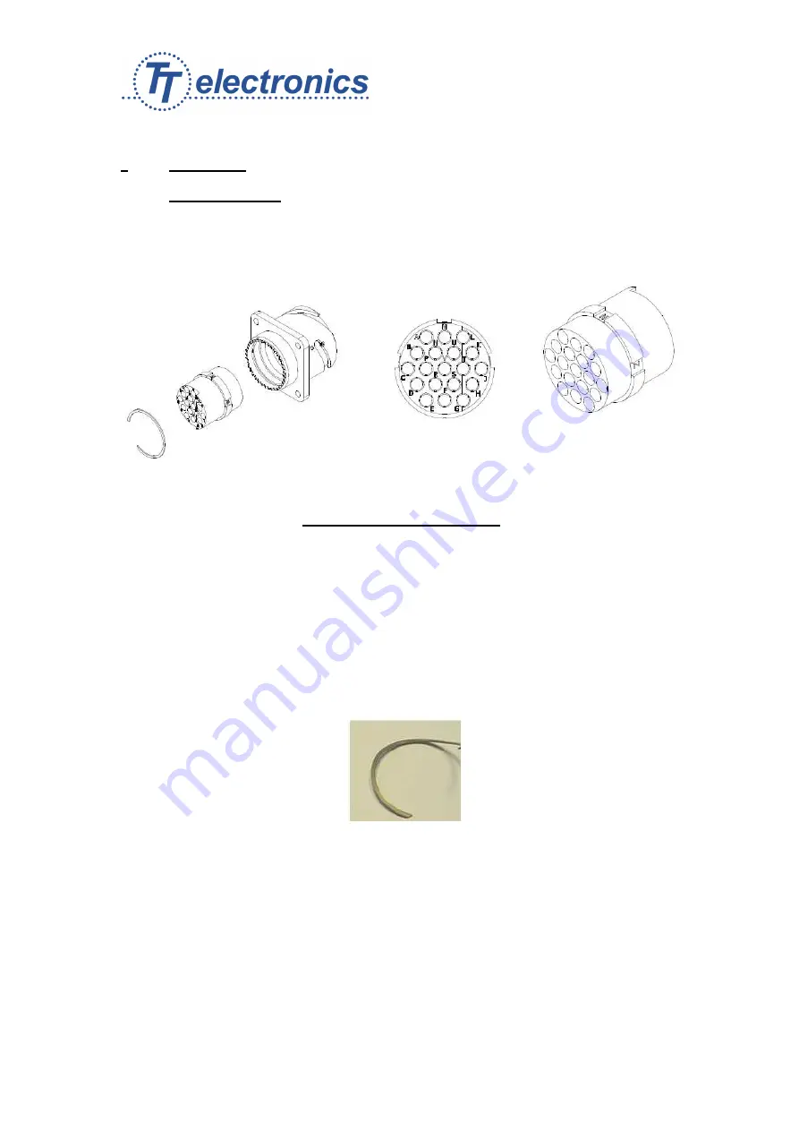
Depending on end user needs, the pin and socket inserts may be supplied separately
to the fixed and free shells to allow the end user to specify the orientation of the
insulator within the connector.
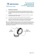
Insert Orientation Components
4.1.2
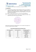
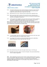
Insulator orientation is used to prevent cross mating of like connectors, which are in
close proximity to each other. It is achieved by firstly having a location key cast into
the fixed and free shells, and secondly by the insulator having a number of location
keyways moulded into the outside shoulder for each desired orientation. Each
position is marked on the insulator and can also be seen on either the front face or
the location keyway.
4.1.3
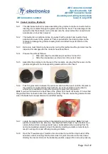
Before the circlip is used, it is best practice to bend the circlip through 90°, so that a
spring washer effect is formed in the circlip. This will not only aid the assembly
process, but will take up any linear movement of the insulator within the shell.
4.1.4
Align the insulator orientation letter required with the key in the shell and press into
place. There may be a slight interference, but it can be pushed to a stop, exposing
the circlip groove in the fixed or free shell.
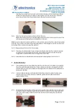
4.1.5
Insert one end of the circlip into the circlip groove, and prize around using a small
screwdriver until the circlip snaps into position. Attempt to push and twist the insulator
to ensure that the circlip is seated correctly.
4.1.6
The Insulator can also be easily removed to orientate it. Locate the chamfered end of
the circlip. Using a small screwdriver prise the circlip out of its groove and “ride” the
screwdriver under the circlip all the way around the shell and it will pop out. The

