AB Connectors Limited
Specification No. 528
ABCIRP Connector Series
Assembly and wiring Instructions
AB Connectors Limited Issue 9: July 2010
Page 13 of 41
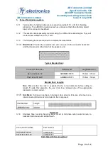
1.2
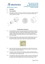
Individual Wire Termination (Crimping Cables)
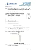
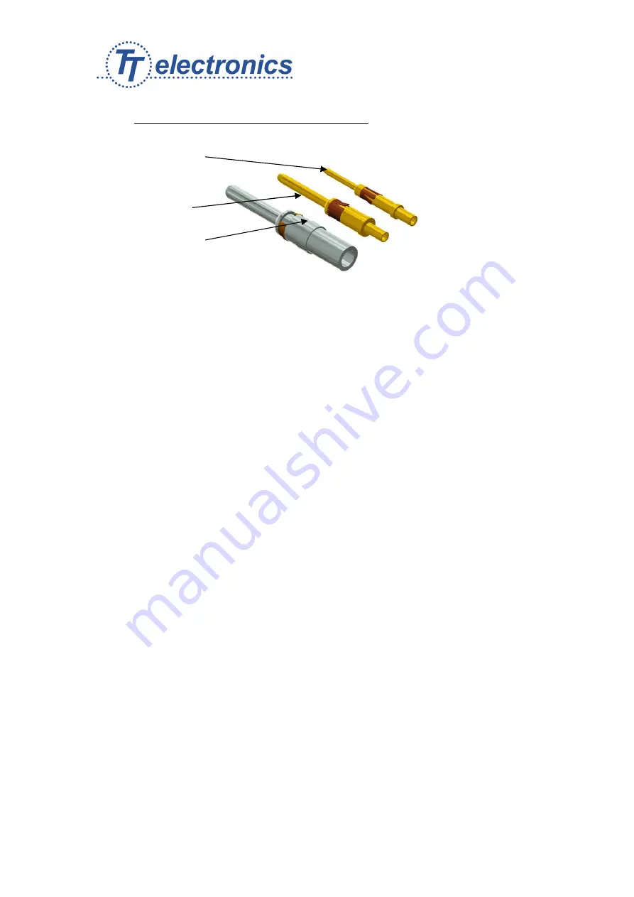
Size 16 contact
Single sided clip.
Size 12 contact
Single sided clip.
Size 8 contact with
Retaining collet.
Crimp Contacts Types
1.2.1
Inspect the conductor to ensure the insulator end is clean and square and the lay of
the strands is not disturbed.
Note: A damaged conductor or strand is not acceptable. Ensure the conductor is
clean before assembly into the contact.
1.2.2
Select the correct crimp tool and turret/locator for the contact to be crimped from the
table in Appendix A, and install the turret/locator onto the crimp tool.
1.2.3
Set the correct tool setting and tool position for the contact as shown in Appendix A.
1.2.4
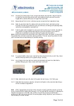
Insert the stripped conductor into the contact crimp bucket. Ensure conductor is fully
pushed in and that insulation is tight to crimp bucket.
1.2.5
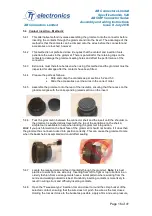
Check inspection hole to see if the conductor strands are visible. If they are not
visible, check the conductor strip length and check for foreign objects in the crimp
bucket.
1.2.6
Operate the empty crimp tool once to ensure the crimping dies are completely open
and there is no misalignment.
1.2.7
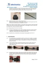
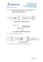
Insert the contact with the conductor installed into the contact-locating hole in the
crimp tool until it 'bottoms' in the locator/turret. Applicable to size 12 & 16 only.
Position the size 8 contact so that the crimp bucket rests on the bottom jaws of the
die set with the back of the contact protruding approximately 2mm over the back of
the die.
1.2.8
Activate the crimp tool through one complete cycle.
1.2.9
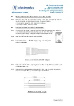
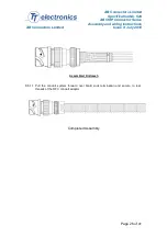
Note: When crimping Size 8 Contacts ensure that the flats of the Hexagonal Die Set
come together.
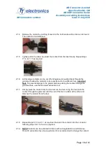
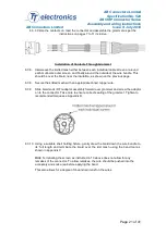
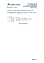
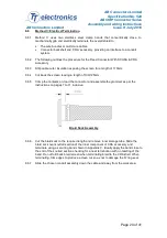
5.2.10 Remove the crimped assembly from the tool and inspect the joint for the correct crimp
location as below.

