
AB Connectors Limited
Specification No. 528
ABCIRP Connector Series
Assembly and wiring Instructions
AB Connectors Limited Issue 9: July 2010
Page 28 of 41
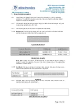
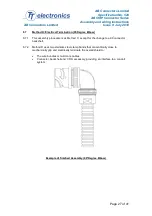
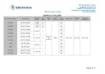
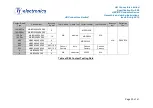
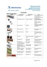
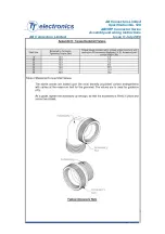
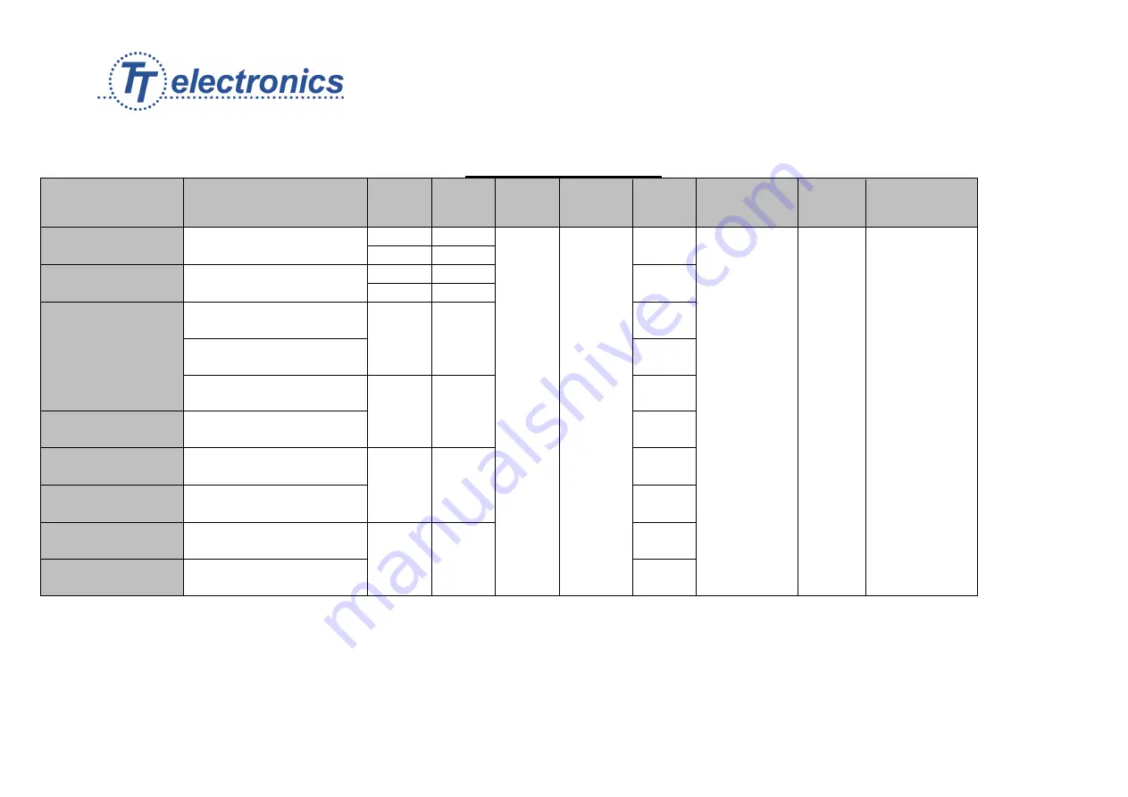
Appendix A: Tooling Data
Contact Size & Type
Part Number
Wire CSA
Sq.mm
Tool
Setting
Crimp
Tool
Turret/
Locator
Tool
Position
Insertion tool
Extraction
Tool
Grommet
extraction tool
16/22 Pin
ABCIRP1622KPK
0.22
2
AF8/WA27F
OR
FT8/WA27E
TH592
Blue
P80 16 ITL
P80 16 ET
P80 16 GET
0.34
3
16/22 Skt
ABCIRP1622KLK
0.22
2
Red
0.34
3
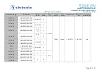
16/20 Pin
ABCIRP1620KPK
0.50/0.75
3
Blue
16/20 Skt
ABCIRP1620KLK
Red
16/18 Pin
ABCIRP1618KPK
0,75/0,93
4
Blue
16/18 Skt
ABCIRP1618KLK
Red
16 Pin
ABCIRP16KPK
0.93/1.5
5
Blue
16 Skt
ABCIRP16KLK
Red
16/14 Pin
ABCIRP1614KPK
1.94/2.08
5
Blue
16/14 Skt
ABCIRP1614KLK
Red


