AB Connectors Limited
Specification No. 528
ABCIRP Connector Series
Assembly and wiring Instructions
AB Connectors Limited Issue 9: July 2010
Page 4 of 41
1
Product Introduction
1.1 General
1.1.1
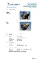
The ABCIRP connector series is based on the MS Bayonet lock series of connectors
conforming to MIL-C-5015 specification. They are interchangeable with all
corresponding MS bayonet lock types and feature identical panel mounting
dimensions.
1.1.2
Designed to operate within a temperature range of -55°C to +125°C, the connector
also meets the mechanical and environmental ratings of BS9522 F0032, VG95234
and NF-F-61-030.
1.1.3
Unlike other MIL-C-5015 bayonet connectors, which utilise insulators bonded into the
shell and or bonded or rubber retained contacts, the ABCIRP connector series
incorporates a Circlip retained solid plastic insulator and metal clip retained contacts.
1.1.4
Stainless steel bayonet pins and rollers riding along the three cam tracks machined
into the receptacle shell achieve the connector coupling. Coupling integrity is
guaranteed by:
•
Firstly having three stainless steel pins at the critical wear points of the receptacle
shell cam-tracks and secondly, by positive lock indicators in the form of
•
An audible click when fully mated.
•
Alignment of coloured dots when fully mated.
1.1.5
ABCIRP connectors are available in 7 sizes from shell size 18 to shell size 40 with
arrangements having 7 to 60 contacts.
1.1.6
Crimp contacts are available in sizes 16, 12 and 8 AWG.
1.1.7
Insulator angular orientation is available for occasions where like connectors are in
close proximity and cross mating has to be avoided. This is achieved by aligning pre-
determined keyways in the insulator with the master key of the plug and receptacle
shell. These angular positions are in accordance with the MIL-C-5015 specification
thereby ensuring compatibility with existing equipment.
1.1.8
The dynamic sealing ring at the base of the plug shell guarantees high reliability and
anti-vibration characteristics including the stainless steel pins at the cam track critical
wear points.
1.1.9
Environmental sealing of mated connectors to IP67 is achieved by compression of
the dynamic seal ring, while integrity at the rear is achieved by the use of an
individual wire seal grommet with membranes being penetrated only when a wire is
present.
1.1.10 Electrical continuity between connectors is achieved by ensuring compression of the
wavy and flat washer assembly at the base of the plug shell.

