TT8900 OPT
–
Installation and Service Manual
Page 19 of 41
4.
Connect the Ground (
green
-
yellow
) conductor to the OPT chassis (by first disconnecting
then reconnecting the door grounding cable).
5.
Make sure the output voltage is set to +26VDC +/- 0.1, or adjust if necessary, using a flat
head screwdriver.
Note:
The Live and Neutral of the AC mains supply conductors should be fitted with crimp-on boot-
lace ferrules and inserted into the DIN rail mains connectors 1 and 2 as shown in
Figure 6
.
The Ground / Earth conductor must be fitted with a crimp-on M6 ring terminal and secured
to the earth stud underneath the supplied M6 flat washer and nut on the OPT chassis.
The DIN rail main connector 3 should NOT be used; It is present for test purposes only.
2.12
Connecting the UPS Battery
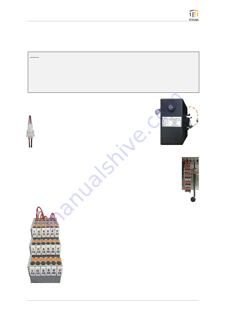
Follow these steps to mount and connect the UPS battery:
1.
Aling the
battery’s
bottom side of the locking mechanism to
the DIN rail.
2.
While pushing the battery upwards, swing the top side
against the DIN rail until it snaps in. (
Figure 7
)
3.
Connect the battery
’s cable
to the OPT’s UPS
.
4.
Switch ON its power button.
2.13
Connecting the Cellular Network Antenna
Follow these steps to connect the Cellular Network Antenna:
1.
After having secured the Cellular Network Antenna, route its cable inside the
OPT through one of its entry holes.
2.
Screw in the SNA connector ensuring it is finger tight.
2.14
Forecourt Connections
The TT8900 OPT comes standard with support for two PEC/NZ pump
communication channels (loops). It can also be optionally fitted with
support for one Gilbarco pump communication channel and/or one Email
pump communication channel.
Alternatively, the OPT can be optionally fitted with a Postec FCC interface
which is an RS232 standard interface. In this case no pump communication
channels are required as the forecourt pump network is connected to the
Postec FCC not the OPT.
All pump communication or RS232 wiring is terminated into the DIN rail
mounted SL protection devices located on the centre of the front DIN rail.
The number and type of SL protection devices fitted to the centre of the
front DIN rail in a particular OPT, and therefore the arrangement of them
on the DIN rail, will depend on whether the following options are included:
Figure 7: UPS Battery
Installation
Figure 8: Cellular
Antenna Connection


