17
OPERATING MANUAL
CAPACITANCE MEASUREMENT
WARNING
!
Please fully discharge all capacitors before measuring (especially
for capacitors with high voltage) to avoid damage to the meter
and personal injury.
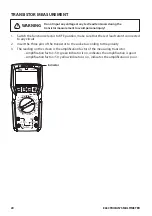
1. Switch the function dial to
100mF
position, the green indicator should be on.
2. Connect the common test lead to COM terminal, then insert red test lead to
Hz
V
Ω
°
C
terminal.
3. Connect the probes to the pins of capacitor.
4. When measuring large volume capacitor, if the yellow indicator is on, it indicates that the
capacitor is being charged, and the green indicator will be on when the capacitor is fully
charged, then wait for the steady reading.
NOTE:
•
If the measured capacitor is short-circuited or the capacitance exceeds the maximum
range, the “OL” symbol will appear on the screen.
•
When measuring large volume capacitors, it may take a few seconds to obtain steady
readings.
•
When there is no input, the meter displays a fixed value (intrinsic capacitance).
•
For small capacitance measurement, this fixed value must be subtracted from the
measured value to ensure measurement accuracy. Or users can choose the relative
measurement function (REL) to automatically subtract the intrinsic capacitance.
True RMS
OFF
Live
NCV 600m
6
60
60
60m
60m
°C°F
Hz%
hFE
600
6k
60k
600k
100mF
6M
60M
60
µ
6
600
600
600m
600m
20
20
1000
1000
V
Ω
A
V
A
Hz
Hz
°C
mA µA
20A
MAX
FUSED
250V max
600mA max
MAX 10sec EACH 15min
FUSED
250V max
20A max
VΩ
Hz
COM
CAT II 1000V
CAT III 600V
SEL
REL
OFF
A
HOLD
NPN
PNP
E
c
b
e
B
C
TTIDM1000V
100mF


