background image

27

OPERATING MANUAL

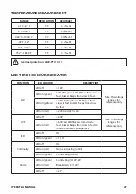
TEMPERATURE MEASUREMENT

RANGE

RESOLUTION

ACCURACY

40

°

C~0

°

C

1

°

C

± (6%+5)

0

°

C~400

°

C

1

°

C

± ( 2%+4)

400

°

C~1000

°

C

1

°

C

± ( 2%+5)

-40° F- 32° F

1° F

± (6%+9)

32 °F~752°F

1° F

± (2%+8)

752°F~1832 ° F

1° F

± (2%+9)

!

Overload protection: 600V-PTC 10.11


LED THREE COLOUR INDICATOR

FUNCTION

LED COLOUR

DESCRIPTION

NCV

LED off

>12V

Note: The voltage 

range is for  

reference only

LED on (green)

12V-48V: green LED flickers from slow to 

fast, buzzer beeps from slow to fast.

LED on (yellow)

>48V-220V: yellow LED flickers from 

slow to fast, buzzer beeps from slow 

to fast

LED on (red)

>220V: red LED is on

LIVE

LED off

<60V

Note: The voltage 

range is for  

reference only

LED on (red}

>60V: red LED flickers from slow to 

fast, buzzer beeps from slow to fast to 

indicate different voltage level

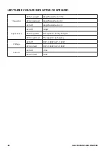
LED

LED off

OL

LED on (green)

<11.1V

Continuity

LED off

OL

LED on (red)

Non-conducting (≤300)

LED on (green)

Conducting (≤30Ω)

Diode

LED on (green)

Conducting (0.12V-2V)

LED on (red)

Breakdown (<0.12V)

LED off

>2V

Summary of Contents for 151476 Series

Page 1: ...ELECTRICIAN S MULTIMETER PART NO TTIDM1000V 151476 OPERATING INSTRUCTIONS...

Page 2: ...tinuity Measurement 16 Capacitance Measurement 17 Frequency Duty Ratio Measurement 18 Temperature Measurement 19 Transistor Measurement 20 Non Contact Voltage Measurement NCV 21 Contact Type Live Neut...

Page 3: ...thin the specifications the machine is rated for Failure to use the machine within the specifications may result in serious injury or death PRODUCT CONTENTS Unpack ensure the following attachments are...

Page 4: ...eter that meet or exceed the safety requirements Comply with local and national safety codes Use personal protective equipment approved rubber gloves face protection and flame resistant clothes to pre...

Page 5: ...and turn off the current to be tested before connecting the meter to the circuit After connecting the circuit reliably turn the current to be tested on Replace the battery as soon as the battery indi...

Page 6: ...torage temperature 20 C 60 C 4 F 140 F Relative humidity 0 C below 30 C 75 30 C 40 C 50 Operating altitude 0 2000m Battery AAA 1 5V x 4 Low battery indication LCD displays symbol EMC a RF field 1V m o...

Page 7: ...V DC voltage measurement V AC voltage measurement A AC current measurement A DC current measurement Live Contact type live neutral wire measurement OFF Shut down Hz Frequency duty radio measurement N...

Page 8: ...battery indicator Diode measurement Continuity measurement Relative value measurement k M Resistance unit mV V Voltage unit A mA A Current unit nF F mF Capacitance unit Hz Frequency unit duty radio C...

Page 9: ...to cycle through the sensing range of EFHI and EFLo In the off state press and hold the SEL REL key then rotate the function dial to turn on the device The product enters the non sleep mode and the b...

Page 10: ...Restart the meter to restore the Auto off function BUZZER WARNING Input AC DC voltage 1000V buzzer warning and red indicator is on high voltage symbol appears indicating that the range is at its limi...

Page 11: ...most cases if the circuit impedance is under 10k the error can be ignored 0 1 The input impedance of DC mV scale is infinite 1000M and it does not attenuate when measuring weak signals so the measure...

Page 12: ...ing to the current being measured connect the common test lead to COM terminal then insert the red test lead to mA A or 20A terminal 2 Connect the test leads with the circuit in series NOTE Readings o...

Page 13: ...ce is greater than 0 5 when the test leads are shorted please check if the test leads are loose or damaged When measuring high resistance at 60M range it takes a few seconds to stabilise the readings...

Page 14: ...to activate the diode measurement 3 Connect the common test lead to COM terminal then insert red test lead to Hz V C terminal 4 Connect the red probe to diode anode black to diode cathode 5 Reading 0...

Page 15: ...L OFF A HOLD NPN PNP E c b e B C TTIDM1000V True RMS OFF Live NCV 600m 6 60 60 60m 60m C F Hz hFE 600 6k 60k 600k 100mF 6M 60M 60 6 600 600 600m 600m 20 20 1000 1000 V A V A Hz Hz C mA A 20A MAX FUSED...

Page 16: ...t lead to Hz V C terminal 3 Connect the probes to the circuit test points 4 Measured resistance 30 The circuit is broken buzzer makes no sound red indicator is on Measured resistance 30 The circuit is...

Page 17: ...If the measured capacitor is short circuited or the capacitance exceeds the maximum range the OL symbol will appear on the screen When measuring large volume capacitors it may take a few seconds to ob...

Page 18: ...cy value is displayed on the screen 4 Short press 2s SEL REL button to perform duty ratio measurement 5 When measuring AC voltage or AC current you can short press 2s the SEL REL button to switch to f...

Page 19: ...button to switch between C F NOTE OL symbol appears when the meter is turned on F 1 8x C 32 True RMS OFF Live NCV 600m 6 60 60 60m 60m C F Hz hFE 600 6k 60k 600k 100mF 6M 60M 60 6 600 600 600m 600m 20...

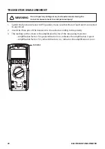
Page 20: ...The reading on the screen is the amplification factor of the measuring transistor Amplification factor 50 green indicator is on indicates the amplification is good Amplification factor 50 yellow indi...

Page 21: ...f sensing level 1 the green indicator will start flashing and the buzzer will beep intermittently According to the intensity of the induced voltage the green indicator flashes with varied frequencies...

Page 22: ...flash and the buzzer will beep According to the voltage value of the live wire the indicator flashes with varied frequencies and the buzzer beeps with different intermittent time The measured voltage...

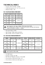
Page 23: ...ce the load is connected 5 digits Max input voltage 1000V Input voltage 1000V audio visual alarm Input voltage 1010V OL appears on LCD AC VOLTAGE MEASUREMENT RANGE RESOLUTION ACCURACY RANGE RESOLUTION...

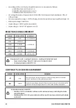
Page 24: ...5 6k 0 001k 0 8 3 60k 0 01k 600k 0 1k 6M 0 001M 1 5 5 60M 0 01M 1 5 25 Measurement result reading of resistance reading of shorted test leads Open circuit voltage about 1V test current is about 0 4mA...

Page 25: ...mF 100 F 10 0D Overload protection 600V PTC Measured capacitance 600nF It is recommended to select REL mode for ensuring accuracy open circuit allows least significant digit 20 DC CURRENT MEASUREMENT...

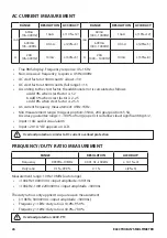
Page 26: ...hen crest factor is 2 5 3 AC current frequency measurement 45Hz 1KHz Min measurement range mA gear position 35mA 20A gear position 5 5A Accuracy guarantee range 1 100 of range open circuit allows leas...

Page 27: ...green LED flickers from slow to fast buzzer beeps from slow to fast LED on yellow 48V 220V yellow LED flickers from slow to fast buzzer beeps from slow to fast LED on red 220V red LED is on LIVE LED...

Page 28: ...ication factor 50 LED off Amplification factor 0 Capacitance LED off 20pF LED on green The capacitor is fully charged LED on yellow The capacitor is charging Voltage LED off DCV 1000V ACV 1000V LED on...

Page 29: ...perature humidity explosive inflammable and strong magnetic field The performance of the meter may deteriorate after dampened BATTERY FUSE INSTALLATION AND REPLACEMENT Battery specification 1 5V x4 AA...

Page 30: ...30 ELECTRICIAN S MULTIMETER...

Page 31: ...31 OPERATING MANUAL...

Page 32: ...be excluded under the Australian Consumer Law You are entitled to a replacement or refund for a major failure and for compensation for any other reasonably foreseeable loss or damage You are also ent...

Reviews: