background image

10-10 

Section 9 - Control Functions - 

Boss R 4520

Deflector

Summary of Contents for Boss R 4520

Page 1: ...40252 16 01 2017 Operator s Manual...

Page 2: ...orkmanship But the company shall not be liable for special indirect or consequential damages of any kind under this contract or otherwise The company s liability shall be limited exclusively to replac...

Page 3: ...Intentionally Left Blank...

Page 4: ...structions 3 1 Keep all safety signs clean and legible 3 1 Section 4 Power Unit Specifications 4 1 Minimum 4 1 Maximum Recommended 4 1 Section 5 Processor Operation 4 1 Processor Installation Instruct...

Page 5: ...Loading Arm 10 8 Deflector 10 10 Bed Dropout 10 12 Flail Drum 10 14 Flail Drum Assembly 10 16 Flail Drum Guards 10 18 Front Cover 10 20 Manifold Block 10 22 Hydraulic Schematic 10 24 Electrical Schem...

Page 6: ...ulch over perennial plants such as strawberries and mushrooms General Information The purpose of this manual is to assist you in safely assembling mounting operating and maintaining your Boss R Read t...

Page 7: ...and No accident prevention program can be successful without the cooperation of the person who is directly responsible for the operation of the equipment If accidents are to be prevented that preventi...

Page 8: ...catch and entangle on moving parts Has annually reviewed all safety instructions Know and follow good work practices when assembling mounting maintaining repairing removing and storing this product W...

Page 9: ...he operator s station Never leave the equipment unattended with the engine running or with this product raised on the loader Be aware of the added weight and width of this product Reduce travel speeds...

Page 10: ...d smooth out any bubbles Instructions Keep all safety signs clean and legible Replace all missing illegible or damaged safety signs Replacement parts for parts with safety signs attached must also hav...

Page 11: ...1 Part DE41711 Crush hazard from bale loading arm Stand clear while arm raised Item 2 Part DE41712 Pinch point hazard from bale loading arm Stand clear while arm in motion High pressure fluid hazard R...

Page 12: ...E41717 Item 8 Part DE41718 Item 6 Part DE41716 Item 5 Part DE41715 Remove key from power unit before attempting repairs on this machine Keep hands away from rotating shaft end Never reach into rotatin...

Page 13: ...ctions pages 3 6 of this manual BEFORE beginning any processor operation DANGER Failure to obey the following procedure will result in death or serious injury Avoid contacting overhead wires WARNING F...

Page 14: ...s or equivalent devices Place this product on a firm level surface that is large enough to safely accommodate this product your power unit and all workers involved in the mounting process Be sure all...

Page 15: ...s to stop before leaving the operator s seat Twine build up should be kept to a minimum to reduce fire hazard and keep the machine in balance Processor Hydraulic Connection SAFETY FIRST READ AND UNDER...

Page 16: ...gns attached must also have safety sign attached Think SAFETY Work SAFELY Deflector Adjustment Needle Valve Adjustment How material is directed can be adjusted by unpinning linkage arms and moving the...

Page 17: ...not operate until the damaged parts have been replaced or repaired Before Each Use Check for loose or badly worn parts Conveyor chain should be adjusted to allow chain slack 1 2 54 cm to 1 3 8 cm Mak...

Page 18: ...sure there are no damaged hoses lines or fittings Wear safety glasses and use metal or wood when searching for leaks Do not use your hands WARNING Hydraulic fluid under pressure can penetrate skin re...

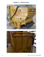
Page 19: ...8 1 Section 8 Grease Points Boss R 4520 Section 8 Grease Points...

Page 20: ...Boss R 4520 Section 8 Grease Points 8 2 Specifications Flange Bearings 6 Once a Week Bale Arm Cylinder Bushings Once a Week Sprockets Once a Week Pins Once a Month...

Page 21: ...black button is in raised position the bed chain will reverse when engaged move bale away from flail motor C A red button that allows the flail drum to turn when pressed or stops flail drum from oper...

Page 22: ...Boss R 4520 Section 10 Part Breakdowns Lists 10 1 Section 10 Part Breakdowns Lists Actual parts may vary slightly from illustrations...

Page 23: ...10 2 Section 9 Control Functions Boss R 4520 Frame...

Page 24: ...3 1 37463 Right Top Cross Member 4 1 37491 Rear Corner Post 5 1 37494 Rear Side Shield 6 1 37499 Main Frame 7 1 40239 Front Angled Corner Post 8 1 41524 Front Side Shield 9 1 41586 Rear Side Panel 10...

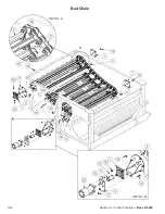
Page 25: ...10 4 Section 9 Control Functions Boss R 4520 Bed Chain...

Page 26: ...1 Grade 5 Zinc 11 9ft side CHAIN ZC60 Chain ZC60 76 2 ZP 12 2 CHAIN ZC60 CON Chain ZC60 76 2 ZP Connector 13 62 HB 1 2 13X3 0 Z5 Hex Bolt 1 2 13 x 3 Grade 5 Zinc Plated Hex Cap Screw NC 14 2 HB 3 8 x...

Page 27: ...10 6 Section 9 Control Functions Boss R 4520 Bed Chain Sliders...

Page 28: ...tion 9 Control Functions 10 7 Bed Chain Sliders ITEM QTY PART NUMBER DESCRIPTION 1 2 41541 Bed Sliders 2 8 HB 5 16 18X1 0 FHSCS Hex Bolt 5 16 18 x 1 Zinc Plated Flat Head Socket Cap Screw 3 8 HNC516 H...

Page 29: ...10 8 Section 9 Control Functions Boss R 4520 Loading Arm...

Page 30: ...Loading Cradle Pin 4 1 37497 Cylinder Pin 5 1 37498 Loading Arm Pin 6 1 40989 Inside Loading Arm 7 2 41540 Loading Arm Slide 8 1 CYL39628 Hydraulic Cylinder 9 20 HB 5 16 18X1 0 FHSCS Hex Bolt 5 16 18...

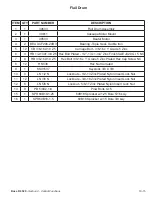
Page 31: ...10 10 Section 9 Control Functions Boss R 4520 Deflector...

Page 32: ...ector 3 2 39356 Deflector Link 4 1 39358 Deflector Strip 5 1 40237 Deflector 6 18 HBC14X34 Hex Bolt 1 4 20 x 3 4 Grade 8 2 Zinc Flange Bolt SAE 7 8 HBC38X114 Hex Bolt Cerrated 3 8 16 x 1 1 4 Case Hard...

Page 33: ...10 12 Section 9 Control Functions Boss R 4520 Bed Dropout...

Page 34: ...for Retainer Bars 2 1 39629 Bottom Pan 3 8 CB 5 16 18X 3 4 Z5 Carriage Bolt 5 16 18 x 3 4 Zinc Plated Grade 5 4 2 HB 1 2 13X3 0 Z5 Hex Bolt 1 2 13 x 3 Grade 5 Zinc Plated Hex Cap Screw NC 5 4 HBC516X3...

Page 35: ...10 14 Section 9 Control Functions Boss R 4520 Flail Drum...

Page 36: ...lated 1 2 13 x 1 3 4 Zinc Finish SAE J429 Gr 5 NC 7 8 HB 3 8 16X1 0 Z5 Hex Bolt 3 8 16 x 1 Grade 5 Zinc Plated Hex Cap Screw NC 8 12 HNC38 Hex Nut Cerrated 9 1 KS41537 Keystock 3 8 X 3 8 10 4 LN 1 2 N...

Page 37: ...10 16 Section 9 Control Functions Boss R 4520 Flail Drum Assembly...

Page 38: ...Drum Shaft 4 2 BS BUSK 1 5 SK Taper Lock Bush 1 1 2 5 16 CMP200113 Flail 6 6 HB 5 16 18X2 0 Z5 Hex Bolt 5 16 18 x 2 Grade 5 Zinc Plated Hex Cap Screw NC 7 16 HB 5 8 18X3 1 2 YZ8 5 8 18 x 3 1 2 Grade 8...

Page 39: ...10 18 Section 9 Control Functions Boss R 4520 Flail Drum Guards...

Page 40: ...Control Functions 10 19 Flail Drum Guards ITEM QTY PART NUMBER DESCRIPTION 1 7 36106 Restrictor Bars 2 38 CB 3 8 16X1 0 Z5 Carriage Bolt 3 8 16 x 1 Grade 5 Zinc 3 15 HBC38X1 Hex Bolt Cerrated 4 53 HN...

Page 41: ...10 20 Section 9 Control Functions Boss R 4520 Front Cover...

Page 42: ...520 Section 9 Control Functions 10 21 Front Cover ITEM QTY PART NUMBER DESCRIPTION 1 1 37495 Front Cover 2 4 HNP 5 16 Panel Nut 5 16 U Type Spring 3 10 HBC516X34 Hex Bolt Cerrated 4 4 HNC516 Hex Nut C...

Page 43: ...10 22 Section 9 Control Functions Boss R 4520 Manifold Block...

Page 44: ...Boss R 4520 Section 9 Control Functions 10 23 Manifold Block ITEM QTY PART NUMBER DESCRIPTION 1 1 37835 Manifold 2 4 HB 3 8 16X1 0 Z5 Hex Bolt 3 8 16 x 1 Grade 5 Zinc Plated Hex Cap Screw NC...

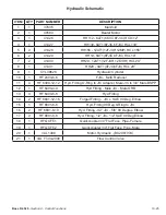
Page 45: ...10 24 Section 9 Control Functions Boss R 4520 Hydraulic Schematic...

Page 46: ...linder 10 1 HF 2403 6 6 FJIC MJIC Reducer 11 4 HF 6400 12 12 Hyd Fitting O Ring to JIC Adapter Male JIC to 3 4 Male BSPP 12 1 HF 6400 4 4 Hyd Fitting Male JIC Male ORB 13 4 HF 6400 6 6 Hyd Fitting 14...

Page 47: ...10 26 Section 9 Control Functions Boss R 4520 Electrical Schematic...

Page 48: ...Intentionally Left Blank...

Page 49: ...11 1 Section 11 Torque Value Charts Boss R 4520 Section 11 Torque Value Charts Imperial Torque Values...

Page 50: ...Boss R 4520 Section 11 Torque Value Charts 11 2 Metric Torque Values...

Page 51: ...lail Drum Guards 10 18 Frame 10 2 Front Cover 10 20 General Information 1 1 Hydraulic Schematic 10 24 Imperial Torque Values 11 1 Instructions 3 1 Keep all safety signs clean and legible 3 1 Loading A...

Page 52: ......
Reviews: