Nitro 275RS
-
Section 2 - Operation 2-1
Section 2 - Operation
Preparation Safety
1. Never use the Nitro Manure Spreader until
you have read and completely understand
this manual and each of the safety messages
found on the safety signs on the Nitro Manure
Spreader.
2. Personal protection equipment including
safety glasses, safety shoes and gloves are
recommended during assembly, installation,
operation, adjustment, maintaining, repairing,
removal, cleaning or moving the unit. Do not
allow long hair, loose fitting clothing or jewelry
to be around equipment.
3. Clear working area of obstacles that might
be hooked or snagged, causing injury or
damage.
4.
Use only in daylight or good artificial light.
5. Be sure machine is properly maintained,
adjusted and in good operating condition.
6. Ensure that all safety shielding and safety
signs are properly installed and in good
condition.
7. Never ride anywhere on the Nitro Manure
Spreader while setting up, operating or
troubleshooting problems.
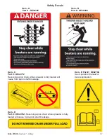
8. The upright beaters on the Nitro can maim
or kill. Always check for bystanders before
engaging the PTO.
THINK SAFETY! WORK SAFELY!
Hydraulic Requirements
The Nitro Manure Spreader requires 16 GPM
hydraulic flow for optimal performance.
PTO / Horsepower Requirements
The Nitro 275 Manure Spreader requires a
minimum of 80 horsepower.
Hook-up / Unhooking
The Nitro Manure Spreader should always be
parked on a level, dry area that is free of debris
and foreign objects. Follow this procedure when
attaching:
1. Clear the area of bystanders and remove
foreign objects from the machine and working
area.
2. Make sure there is enough room to back the
tractor up to the hitch pole.
3. Start the tractor and slowly back it up to the
hitch point.
4. Stop the tractor engine, place all controls in
neutral, set park brake and remove ignition
key before dismounting.
5. Use the hitch pole jack to raise or lower the
pole to align with the drawbar.
6. Install a drawbar pin with provisions for a
mechanical retainer. Install the retainer.
7. Install a safety chain between the tractor
drawbar and the hitch pin.
8. Connect PTO driveline to tractor.
9. Connect the hydraulics. To connect, proceed
as follows:
• Use a clean cloth or paper towel to clean the
couplers on the ends of the hoses. Also clean
the area around the couplers on the tractor.
• Remove the plastic plugs from the couplers
and insert the male ends.
NOTICE
: If the direction of motion is wrong,
reverse the couplers.
10. Raise the hitch jack.
11. When unhooking from the tractor, reverse the
above procedure.
NOTICE: Occasionally air
may become trapped in the hydraulic circuit,
making it necessary to “bleed” the circuit.
To perform this operation cycle the hydraulic
several times or especially on older tractors,
temporarily loosen an easily accessible hose
fitting enough to allow any trapped air to escape
while cycling the hydraulics. Retighten fitting.
Summary of Contents for Nitro 275RS
Page 1: ...40299 Rev 1 1 18 04 2018 Operator s Manual Parts Manual...
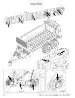
Page 24: ...4 4 Section 4 Troubleshooting Maintenance Nitro 275RS Grease Points...
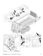
Page 25: ...Nitro 275RS Section 4 Troubleshooting Maintenance 4 5...
Page 26: ...Intentionally Left Blank...
Page 27: ...Nitro 275RS Section 5 Parts Breakdowns Lists 5 1 Section 5 Parts Breakdowns Lists...
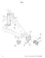
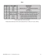
Page 28: ...5 2 Section 5 Parts Breakdowns Lists Nitro 275RS Hitch...
Page 30: ...5 4 Section 5 Parts Breakdowns Lists Nitro 275RS Front Shields...
Page 32: ...5 6 Section 5 Parts Breakdowns Lists Nitro 275RS Front Apron Drive...
Page 34: ...5 8 Section 5 Parts Breakdowns Lists Nitro 275RS Driveline...
Page 36: ...5 10 Section 5 Parts Breakdowns Lists Nitro 275RS Rear Apron Drive...
Page 38: ...5 12 Section 5 Parts Breakdowns Lists Nitro 275RS Endgate...
Page 40: ...5 14 Section 5 Parts Breakdowns Lists Nitro 275RS Beaters...
Page 42: ...5 16 Section 5 Parts Breakdowns Lists Nitro 275RS Floor Side Boards...
Page 44: ...5 18 Section 5 Parts Breakdowns Lists Nitro 275RS Single Axle...
Page 46: ...5 20 Section 5 Parts Breakdowns Lists Nitro 275RS Tandem Axle w o Scales...
Page 48: ...5 22 Section 5 Parts Breakdowns Lists Nitro 275RS Tandem Axle w Scales...
Page 50: ...5 24 Section 5 Parts Breakdowns Lists Nitro 275RS Apron Runners...
Page 52: ...5 26 Section 5 Parts Breakdowns Lists Nitro 275RS Hydraulic Layout...
Page 54: ...Intentionally Left Blank...
Page 56: ...6 2 Section 6 Optional Features Nitro 275RS Light Kit Assembly...
Page 58: ...6 4 Section 6 Optional Features Nitro 275RS Light Kit Wiring Harness...
Page 60: ...6 6 Section 6 Optional Features Nitro 275RS Flow Control Hydraulics...
Page 62: ...6 8 Section 6 Optional Features Nitro 275RS Electric Flow Control Wiring...
Page 64: ...6 10 Section 6 Optional Features Nitro 275RS N750LC GT400 N750LCNT460 Scales...
Page 65: ...Nitro 275RS Section 6 Optional Features 6 11 N750LCNT8000 Scales...
Page 67: ...Nitro 275RS Section 7 PTOs 7 1 Section 7 PTOs...
Page 68: ...7 2 Section 7 PTOs Nitro 275RS 39850 PTO 375 450 525 600 750 V80 141P028359 028028 CV80 CLS...
Page 70: ...7 4 Section 7 PTOs Nitro 275RS 39852 PTO 600 750 T60 086P265011 306028 CLS 2500NM...
Page 72: ...VII Torque Value Chart Imperial Nitro 275RS Torque Value Chart Imperial...
Page 73: ...Nitro 275RS Torque Value Chart Metric VIII Torque Value Chart Metric...
Page 76: ......


