background image

Maintenance 


60 


50-hour maintenance / weekly 

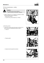
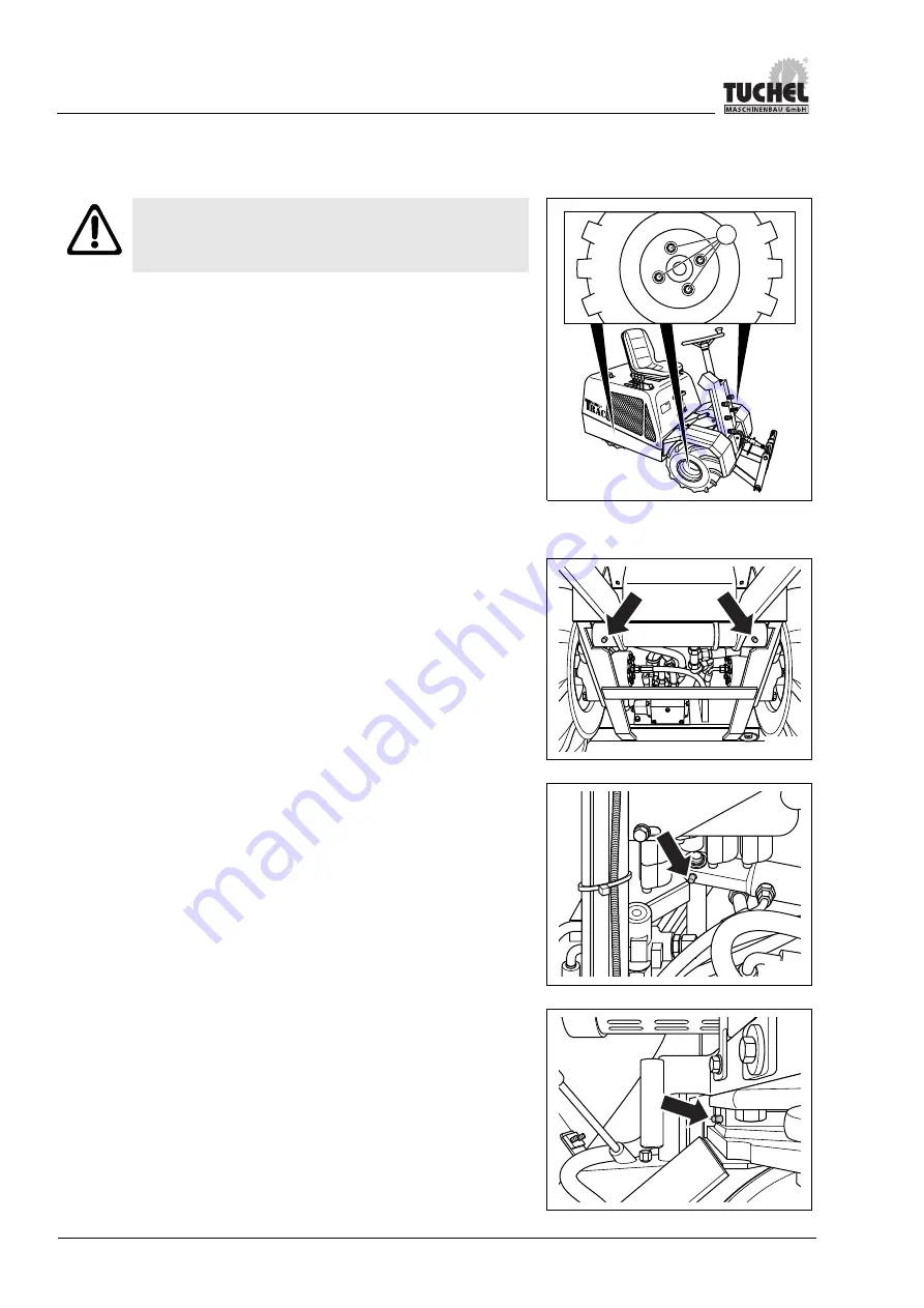
Wheel nuts 


WARNING! 

Loose wheel nuts can cause accidents. 

  Check the wheel nuts regularly for tightness.


000046

1


1.  Check the wheel nuts (1) for tightness and tighten the wheel 

nuts using a torque wrench to 70 Nm an. 
–  Daily in the first week 
–  Thereafter every 50 operating hours or weekly 


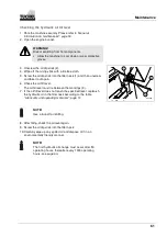
Lubricating points 

1.  Lubricate the following points with grease according to the 

table 

"Lubricants and operating

 materials

"; page 51

  Lower link 


000014


  Steering cylinder 


000015


  Steering knuckle (steerable rear wheel) 


000016


Summary of Contents for Tuchel-Trac Trio

Page 1: ...perating manual is only valid in combination with the corresponding operating manual of the combustion engine diesel Kubota The supplied delivery inspection form is to be filled out completely and returned to the manufacturer ...

Page 2: ... machine 14 Climbing on and off 14 Protecting against injuries 14 Working with high temperatures 15 Fire prevention and fire fighting 15 Accessory equipment 16 Battery 16 Before starting the engine 16 Operating the machine 17 Transporting 19 Safety measures during maintenance 20 Before performing maintenance work 20 During the maintenance 21 3 Technical data 23 Dimensions 23 Work values 23 Engine ...

Page 3: ...gulations when driving 40 Driving forwards 41 Braking 41 Driving in reverse 42 Steering and turning 42 Turning off the engine 43 Working with accessory equipment 44 Safety regulations when working with accessory equipment 44 Installing the accessory equipment 44 Removing the accessory equipment 46 Placing out of operation 47 Turning off of the machine safely 47 Storing the machine over longer peri...

Page 4: ...nts 60 Checking the hydraulic oil fill level 61 250 hour maintenance 62 Changing the hydraulic filter 62 1000 hour maintenance yearly 63 Changing the hydraulic oil 63 Maintenance as needed 64 Changing the fuse 64 Service 65 8 Troubleshooting 69 Engine 69 Brake 69 Traction drive 70 Working hydraulics 71 9 Index 72 ...

Page 5: ... and observe the respective safety and warning instructions in this manual and on the machine before using or servicing the machine Before placing the machine into operation all machine operators must make themselves familiar with the handling of this machine using this operating manual The safety regulations are to be strictly adhered to Adherence to the valid safety regulations for your country ...

Page 6: ...eplacement manual can be requested from Tuchel Maschinenbau GmbH at any time If the machine is sold the operating manual must be transferred to the new owner The owner of the machine bears the responsibility for the following points Every operator must be of at least legal minimum age and physically as well as mentally fit to reliably fulfil the tasks assigned to them Every person who operates or ...

Page 7: ... EC and is authorised to carry the CE mark Furthermore the harmonised European Norms DIN EN 12100 DIN EN 982 DIN EN 1553 and BGV D 29 were used for the development of the machine These are documented in the EU declaration of conformity Please see the back side of this operating manual for the manufacturer address NOTE The declaration of conformity is depicted on the following page ...

Page 8: ...schine Fabrikat Tuchel Trac Trio Typ 1601 Maschinennummer übereinstimmt mit den Bestimmungen folgender EG Richtlinien Maschinen Richtlinie 2006 42 EG EMV Richtlinie 2004 108 EG Elektromagnetische Verträglichkeit Angewendete Normen und technische Spezifikationen DIN EN ISO 12100 1 2003 DIN EN ISO 12100 2 2003 DIN EN 13857 2008 DIN EN 349 1993 DIN EN 982 1996 DIN EN 1553 1999 DIN EN 703 2005 Salzber...

Page 9: ...the purpose defined in Chapter Description overview page 25 and the approved components Any other use does not comply with the regulations requirements or intended use The manufacturer cannot assume liability for any damages resulting from an unintended use The user owner alone bears the risk for this Follow the corresponding safety instructions and working steps from this operating manual and the...

Page 10: ...bserved sufficiently WARNING Bodily injury Identifies risks which can cause physical injury if the respective warning was not observed or was not observed sufficiently CAUTION Light injuries Identifies risks that can cause light bodily injury This is the caution warning It warns you about the risk of property damage It differs from the hazard warning in order to distinguish between property damage...

Page 11: ...operating manual and safety instructions before placing into operation Read and observe the operating manual and safety instructions before performing any maintenance work Do not stay in the area of a raised and unsecured load The transporting of passengers is not permitted Caution with escaping high pressure fluid Observe the safety instructions in the operating manual Never step in the hazard ar...

Page 12: ...have these warning labels There is the risk that hands could be crushed pulled in or otherwise be injured There is the risk that hands could be pulled in by rotating fans or otherwise be injured Fire smoking and open flame forbidden This figure is used where there is a significant fire hazard due to existing substances fuels battery acid What to do No sources of ignition may be brought into or ari...

Page 13: ...hed to the machine Make sure that damaged guards and covers are repaired Under no circumstances may any safety installations be removed such as e g the protective grating on the air filter Clothing You may not wear loose fitting clothing jewellery or wear your hair open These items could get caught in control elements or in moving parts such as fans and cause severe injuries Change clothing that i...

Page 14: ...the holding brake and turn off the engine Always remove the ignition key and close the ignition switch with the locking cap before you leave the driver s seat Keep the ignition key in safe custody Climbing on and off Never jump onto or off of the machine Never climb onto or leave a running machine Always climb onto the machine from the left side Do not hold onto control levers and do not step on t...

Page 15: ...rotective equipment Fire prevention and fire fighting Fuels and oil are easily inflammable and can cause fires Do not come near inflammable materials with an open flame Turn off the engine before refuelling and do not smoke Perform refuelling or refilling of oil in a sufficiently ventilated location Close all screw caps tightly Check the fuel system and hydraulic system for leaks Have leaks repair...

Page 16: ...chinenbau GmbH assumes no liability for injuries accidents or damages that are caused by the use of unapproved accessory equipment Battery Work on the battery may only be performed by specialist repair shops Before starting the engine Safety at work Before starting the operation check the working area for dangerous working conditions Inspect the surface and condition of the ground at the site and ...

Page 17: ... to protect yourself from dust and limited visibility Avoid jerky starts turns or stops when equipment is attached to the machine High visibility When working in dark areas provide additional lighting for the working area Stop working when visibility is poor e g during fog rain or snow and wait until the visibility has improved enough to ensure that work can continue safely Working on snow or blac...

Page 18: ...lways at the sole discretion of the operator The machine is not suitable for operation on slopes or embankments Use vehicles which are specifically developed for this purpose On a slope a number of factors such as angle of slope subsurface mode of operation accessory equipment etc can lead to the machine sliding or tipping over If the machine is operated in a hillside situation the operator alone ...

Page 19: ...king cap Use only a fork lift or a wheel loader with stacker equipment fork prongs to lift the vehicle onto the loading space Adjust the prongs so that the prongs can be positioned sufficiently wide enough apart between front and rear axle see dimension X in the adjacent drawing Drive with the prongs underneath the hydraulic tank without damaging the bleed screw 1 of the hydraulic tank in the proc...

Page 20: ... Use appropriate tools only The use of damaged poor quality faulty or makeshift tools will cause injuries Safety relevant parts The parts are subject to a normal wear and must be replaced at regular intervals even if they are not yet defective Safety relevant parts are Fuel system Fuel hose overflow hose and tank cap Hydraulic system All hydraulic hoses Protective grating Fan Defective parts must ...

Page 21: ...fluids immediately Take the surface temperature into account See Working with high temperatures page 15 Always replenish fuel and oil in a sufficiently ventilated area Clean the area around the fill opening before refilling Close the fill locations after refilling Do not allow oil or fuel to get into the soil or ground water Dispose of in an environmentally friendly manner High pressure hoses You ...

Page 22: ...protective glasses and gloves and always use a piece of paper or wood to check for oil leakages If you have been struck by a high pressure oil jet contact a physician immediately and explain the details of the incident Fan and V belt Always keep a sufficient distance to rotating parts and ensure that nothing can get caught up in them Parts that get into the fan can be cut off or flung off Do not w...

Page 23: ... kg Approved gross vehicle weight 1 200 kg Braking system Mechanical holding brake Tyre size air pressure 18x8 50 8 1 50 bar Tractor tyres 19x9 50 8 1 68 bar Tyres with grass profile option Speed 2 driving speeds 4 4 km h and 11 3 km h Power train Hydraulic All wheel 3 wheel motors Steering system Hydraulic Gradient angle max 40 Weight 642 kg ...

Page 24: ...r Displacement volume 25 l min at 3200 rpm Hydraulic oil tank capacity 65 l Drive circuits 1x double acting drive circuit 1x leak oil 1x double acting drive circuit option Lifting power 350 kg at the crosspoint Additional equipment option Towing hitch Towing capacity 250 kg Supporting load 50 kg Noise emission Noise level at the machine measured in dB A Measuring position 1 2 3 4 000021 1 2 3 4 1 ...

Page 25: ...ed to the hydro motor of the traction drive the hydraulic cylinder of the steering and the lower link as well as the drive circuits of the working hydraulics The traction drive and the working hydraulics are connected to the same hydraulic tank A safety switch integrated into the driver s seat blocks the hydraulic drive circuit as soon as the driver stands up from the seat In order to activate the...

Page 26: ...nections 4 Accelerator pedal 5 Type plate 6 Driver s seat 7 Filler neck for hydraulic oil 8 Rear wheel steerable 9 Engine bonnet locking mechanism 10 Front wheels 11 Lower link 12 Exhaust system 13 Engine bonnet 14 Steering wheel 15 Instrument panel 16 Holding brake 17 Control lever 18 Filler neck for diesel fuel 19 Holder for rear weights ...

Page 27: ...ntrol lever 1 Control valve for pull away braking speed 2 Lift lower control lever 3 Control lever L2 option 4 Control lever L3 5 Driving speed lever 6 Hand throttle lever 000006 1 2 3 4 5 6 Display panel 1 Fuel Warning indicator 2 Preheating Control display 3 Tachometer 4 Engine oil pressure Warning indicator 5 Coolant temperature Warning indicator 6 Battery Control display 7 Air filter Warning i...

Page 28: ... shows the engine speed in the range from 0 5000 rpm 4 Engine oil pressure Warning indicator If the engine oil pressure falls below the permitted value the indicator lights up and a warning buzzer sounds ATTENTION Damage to the engine Stop the machine immediately and turn off the engine Proceed as described in the combustion engine operating manual 5 Coolant temperature Warning indicator The indic...

Page 29: ...minated In this case the air filter cartridge must be cleaned or replaced Proceed as described in the combustion engine operating manual 8 Operating hours counter The operating hours counter displays the total operating hours The operating hours are only counted for running engine only independently from whether the machine is moving 9 Ignition switch start switch The engine is preheated and start...

Page 30: ...ion 3 Connecting plug for control lever L3 flow line I 4 Connecting sleeve for control lever L3 return line II 5 Connecting sleeve for overflow oil line free return 000043 2 1 4 3 5 Quick change unit 1 Centring spikes 2 Upper link 3 Locking pin 4 Locking bar 5 Locking bolt 000005 1 2 3 4 5 Accessories 1 Holder for rear weights 2 Towing hitch 3 Rear weights 000030 2 1 3 ...

Page 31: ...rb weight kg Enter the machine data here so that the specifications are readily available at any time The complete identification marking has the value of a certificate and may not be modified or made irrecognisable The identification marking must be replaced if it is damaged or has faults ...

Page 32: ... surface warning sticker 5 Hydraulic oil sticker 6 Diesel fuel sticker 7 Hydraulic connections symbols 8 Horn signal symbol 9 Control levers symbols 10 Direction of motion symbol 11 Holding brake symbol 12 Pull away brake symbol 13 Hand throttle symbol 14 Hearing protection mandatory sign 15 Open fire prohibition sign 16 Immer die Nase vorn logo 17 Tuchel manufacturer nameplate 18 TuchelTrac manuf...

Page 33: ...y from the driver s seat Inwards The lever is moved inwards towards the driver s seat The lift lower control lever 1 is used to raise or lower the accessory equipment Do not move the lever jerkily 1 Operate the lever 1 over the notch outwards The accessory equipment lowers The lever remains in this indexed position or floating position The accessory equipment follows the contour of the ground If t...

Page 34: ...k e g for inclination of a snow plough blade or a road sweeper 000024 1 Control lever L3 The hydraulic circuit L3 from the accessory equipment is activated with the control lever L3 1 Do not move the lever jerkily 1 Press the lever 1 outwards over the notch in position II The lever stays in the indexed position The flow line of the hydraulic circuit is free and the hydraulic oil flows through the ...

Page 35: ...n 000026 1 Control valve for pull away braking speed The driving behaviour during pull away and braking is set using the control valve 1 and thus also influences the pull away and braking speed 1 Turn the control valve anti clockwise The machine slows down and slowly comes to a standstill 2 Set the driving behaviour according to your own discretion for your particular working application For an up...

Page 36: ...may only be operated in a technically sound state and for its intended purpose in accordance with regulations ATTENTION Damage to the machine thorough excessive loads Observe the maximum axle load limits Break in time The following guidelines apply during the first 50 operating hours ATTENTION Damage to the machine During the first 50 hours of operation 70 of the full load may not be exceeded Choo...

Page 37: ... may not exhibit any damages or leakages Damaged hoses must be replaced Accessory equipment must be attached properly and function according to its separate operating manual Is the accessory equipment securely interlocked Are the stepping surfaces clean The tyres may not be damaged or worn out Checking the fill levels Is the tyre pressure correct Is there sufficient fuel in the tank Is the engine ...

Page 38: ...est With your back leaning against the backrest you must be able to operate the full range of the accelerator pedal 2 in all directions and turn the steering wheel in its full range in all directions You must be able to securely reach and operate all operating elements WARNING Risk of accident by unintended operation e g of the accelerator pedal Do not adjust the driver s seat while driving 6 Pull...

Page 39: ...OFF ON GL ST 1 2 ATTENTION Damage to the machine Never operate the starter longer than 15 seconds If the engine does not start up during this time wait at least two minutes before attempting to start it again If the engine does not start up after two attempts refer to Troubleshooting page 69 Never turn the ignition key to start while the engine is running During the first 50 hours of operation 70 ...

Page 40: ...ation and do not be tempted to enter into a safety risk When using accessory equipment special conditions apply see Installing the accessory equipment page 44 Refrain from any working method which affects the standard safety of the machine DANGER Toppling risk when driving on inclinations Always keep a sufficient distance to ditches or steep slopes and embankments Never turn while on inclinations ...

Page 41: ...e foot contact switch 2 to activate the second drive position 5 Press the accelerator pedal 1 forwards slightly The machine moves forwards 000033 1 2 Braking There is no separate service brake The machine brakes automatically as soon as the accelerator pedal is in the neutral position 1 Release your foot from the accelerator pedal 1 The machine is braked 000034 4 ATTENTION Damage to the machine Do...

Page 42: ...o activate the second drive position 2 Press the accelerator pedal 1 backwards slightly The machine moves backwards 000035 1 2 Steering and turning The steering forces change if accessory equipment and rear weights are attached 1 Steer the machine by turning the steering wheel 1 The turning radius is specified in chapter Technical data page 23 000036 1 DANGER Toppling risk when driving on inclinat...

Page 43: ...ace all operating levers of the working hydraulics in the null position 000037 1 3 2 NOTE Do not turn off the engine abruptly after heavy loading Allow the engine to run for about a minute to increase the service life of the engine Safekeeping of the ignition key 1 Turn the ignition key to the left to the OFF position 2 Remove the ignition key 3 Close the locking cap of the ignition switch 4 Keep ...

Page 44: ...ent Before attaching accessory equipment the quick release couplings must be depressurised After the installation check the functioning of the accessory equipment before placing into operation for the first time Ensure that the accessory equipment is always in a secure position and that the holding brake is engaged before leaving the machine Installing the accessory equipment 1 Activate the holdin...

Page 45: ...nsure that the holder is secured 13 Connect the hydraulic hoses from the accessory equipment to the quick release couplings of the machine according to the identification marking L2 and L3 Drive circuit L2 000044 L2 I L3 I L3 II L2 II 1 NOTE Use the overflow oil line if the hydraulic oil is to only flow in one direction through the accessory equipment e g with a free turning road sweeper rotary mu...

Page 46: ...essory equipment 8 Unlock the quick change unit Pull the locking shaft 1 on the handle outwards Turn the locking shaft so that the locking pin 2 hooks behind the locking bar 3 9 Start the engine 10 Release the holding brake 000039 1 2 3 11 Operate the lift lower control lever 1 to lower the quick change unit to the ground far enough so that the accessory equipment unhooks 000040 1 WARNING On uneve...

Page 47: ...olding brake 1 2 Press the lift lower control lever 2 outwards to lower the quick change unit or the accessory equipment to the ground 000037 1 3 2 Safekeeping of the ignition key 1 Turn the ignition key to the left to the OFF position 2 Remove the ignition key 3 Close the locking cap of the ignition switch 4 Keep the ignition key in safe custody The machine is secured against unauthorised startin...

Page 48: ...ngine compartment and allow the machine to dry see chapter Maintenance Park the machine in a dry clean and frost free location We suggest that you also cover the machine with a tarp to protect it against dust Fill up the fuel tank Grease the machine Change the engine and hydraulic oil While out of service Start the engine and let it run once a month Drive the machine over a short distance so that ...

Page 49: ... direct contact Observe the applicable provisions and safety regulations for the respective lubricant and consumable item Wear suitable protective clothing All safety information from chapter Safety must be taken into account and applied The industrial safety and accident prevention regulations of the relevant Employers Liability Insurance Association are binding Safety relevant parts Damaged safe...

Page 50: ...he ignition key to the left to the OFF position 2 Remove the ignition key 3 Close the locking cap of the ignition switch 4 Keep the ignition key in safe custody The machine is secured against unauthorised starting 2 3 000038 1 OFF ON GL ST Battery Maintenance work may only be performed by qualified personnel Engine The maintenance work is described in the provided operating manual of the combustio...

Page 51: ...s Before draining the operating materials or changing the filter wait until the engine has cooled down to approx 60 C Do not drain oils when they are cold For engine related maintenance please refer to the operating manual of the combustion engine If necessary secure the machine with suitable supports Never work underneath an inadequately supported machine Lubricants that are not listed in the fol...

Page 52: ...isted in the operating manual or the replacement parts list of the combustion engine Please provide the following information when ordering replacement parts Engine type Engine no Article no Article Supplement 1 00 IP 00023 Oil filter cartridge 2 00 IP 00020 V belt 3 00 IP 00028 Air filter element 4 00 IP 00027 Fuel filter 5 00 ER 00025 Suction filter element Drive valve 6 00 ER 00026 Suction filt...

Page 53: ...not listed here Please refer to the accompanying operating manual of the combustion engine The intervals are classified according to the following types Service inspection after Operating hours Type 50 weekly A every 250 B 1000 yearly C Whichever occurs first The inspection intervals A must be performed weekly or after 50 operating hours You do not require a certification from a specialist repair ...

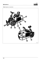
Page 54: ...Maintenance 54 Maintenance overview 000029 6 2 1 1 7 3 4 8 8 5 ...

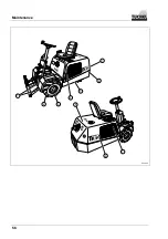
Page 55: ...0 operating hours and retighten if necessary 5 60 Engine bonnet steps mounting bolts Check for tightness and retighten if necessary Wheel house mounting bolts Wheel house step accelerator pedal operating levers For heavy soiling clean in between the operation Radiator for engine coolant radiator cooling fins Free the fins of dirt 58 50 hour maintenance weekly Interval Type A Check point Maintenanc...

Page 56: ...Maintenance 56 000029 6 2 1 1 7 3 4 8 8 5 ...

Page 57: ...al Type B Check point Maintenance work Pos Page Hydraulic filter Replace 8 62 Air filter Replace See operating manual of the combustion engine 1000 hour maintenance yearly Interval Type C Check point Maintenance work Pos Page Hydraulic oil Replace Check oil fill level after test run 2 63 Hydraulic tank Leak tightness check Seek out a specialist repair shop Hydraulic hose lines Hydraulic connection...

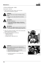
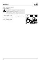
Page 58: ...TION Damage to the electrical system Risk of short circuit Do not allow water to reach electrical components 2 Clean the outside of the machine using a cloth and use water soluble cleaning agents and water 3 Clean the following locations in particular Stepping surfaces 1 Accelerator pedal 2 Operating levers elements 3 to 7 000045 2 3 5 4 1 7 6 WARNING Risk of injury when working with compressed ai...

Page 59: ...ck the tyre pressure under the following conditions On cold tyres before starting work Without accessory equipment Without rear weights Without trailer The tyre pressure is specified in chapter Technical data page 23 2 Check the tyres for damage or foreign objects If necessary remove the foreign object from the tyre profile Damaged tyres must be replaced by a specialist dealer ...

Page 60: ... nuts 1 for tightness and tighten the wheel nuts using a torque wrench to 70 Nm an Daily in the first week Thereafter every 50 operating hours or weekly Lubricating points 1 Lubricate the following points with grease according to the table Lubricants and operating materials page 51 Lower link 000014 Steering cylinder 000015 Steering knuckle steerable rear wheel 000016 ...

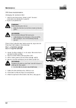
Page 61: ...d take it out again 6 Check the oil fill level The oil fill level must lie between the markings 3 7 If the oil fill level does not reach the specified level replenish the hydraulic oil in the filler neck according to the table Lubricants and operating materials page 51 000008 2 1 3 NOTE Use a funnel for refilling 8 After filling check the oil level again 9 Screw the oil dip stick into the filler n...

Page 62: ...et These are to be replaced in the same way Pos 1 short filter cartridge Pos 2 long filter cartridge 3 Loosen the filter cartridge 1 or 2 using a filter wrench and unscrew the filter cartridge 4 Free the oil filter holder sealing surface of dirt 5 Oil the rubber gasket of the new filter cartridge slightly 6 Screw on the filter cartridge by hand until the gasket sits 000013 1 ATTENTION Tightening t...

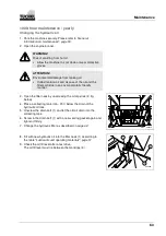
Page 63: ...ly friendly manner 3 Open the filler neck by unscrewing the oil dip stick 2 fig below 4 Place a collecting tank min 70 l below the drain of the hydraulic oil tank 5 Unscrew the drain bolt 1 and let the old oil drain into the collecting tank 6 Screw in the drain bolt 1 with a new sealing gasket again and tighten it firmly 7 Change the hydraulic filter as described on page 62 000048 1 8 Fill with ne...

Page 64: ...The functioning of the machine is not assured if unapproved components are used Use only original replacement parts 1 Open the engine bonnet 2 Replace the defective fuse 1 with a new original fuse from Hella Order no 8JS 711 687 002 3 Close the engine bonnet 000011 1 ...

Page 65: ...__________________________________ Signature Company stamp performance of the maintenance Transfer Operating hours Inspection B C Date __________________ _______________________________________________ Signature Company stamp performance of the maintenance Transfer Operating hours Inspection B C Date __________________ _______________________________________________ Signature Company stamp perform...

Page 66: ..._____ _______________________________________________ Signature Company stamp performance of the maintenance Transfer Operating hours Inspection B C Date __________________ _______________________________________________ Signature Company stamp performance of the maintenance Transfer Operating hours Inspection B C Date __________________ _______________________________________________ Signature Co...

Page 67: ..._____ _______________________________________________ Signature Company stamp performance of the maintenance Transfer Operating hours Inspection B C Date __________________ _______________________________________________ Signature Company stamp performance of the maintenance Transfer Operating hours Inspection B C Date __________________ _______________________________________________ Signature Co...

Page 68: ..._____ _______________________________________________ Signature Company stamp performance of the maintenance Transfer Operating hours Inspection B C Date __________________ _______________________________________________ Signature Company stamp performance of the maintenance Transfer Operating hours Inspection B C Date __________________ _______________________________________________ Signature Co...

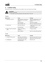
Page 69: ... Fuel tank empty Refill with fuel diesel Battery defective flat Seek out a specialist repair shop 2 Engine stops Switch was activated Check that no parts are located on the switch Fuel tank empty Refill with fuel diesel 3 Starter only turns the engine slowly Charge of the battery is insufficient Charge the battery Starter defective Seek out a specialist repair shop Brake Malfunction Cause Remedy 1...

Page 70: ...fective Seek out a specialist repair shop Hydraulic filter contaminated Replace hydraulic filter Control valve set incorrectly Adjust the control valve setting Accelerator pedal blocked Remove object in the area of the pedal 3 The machine moves jerkily Oil level in the hydraulic tank too low Replenish hydraulic oil Hydraulic malfunction Seek out a specialist repair shop 4 Hydraulic oil overheated ...

Page 71: ... hydraulic oil and fill with required hydraulic oil Oil level in the hydraulic tank too low Replenish hydraulic oil 4 Cylinders move jerkily Oil level in the hydraulic tank too low Replenish hydraulic oil 5 Cylinders move jerkily Oil level in the hydraulic tank too low Replenish hydraulic oil 6 Operating levers of the working hydraulics not functioning Driver not seated on the seat The driver must...

Page 72: ...se 17 42 Driving on embankments 18 Driving speed 35 During the maintenance 21 E Emergency lowering 19 Engine 24 50 69 Engine compartment 51 Engine oil pressure Warning indicator 28 Exposure to high pressure oil 22 F Fan and V belt 22 Fill levels 37 Fire prevention and fire fighting 15 Foot contact switch 33 Foreword 5 Fuel Warning indicator 28 Fuse 64 G General information on maintenance 50 Genera...

Page 73: ...s 20 49 Service 65 Service intervals 53 Settings before starting 38 Starting conditions 39 Starting procedure 39 Starting the engine 39 Steering 42 Storing the machine over longer periods of time48 T Tachometer 28 Technical data 23 Tools 20 Traction drive 70 Transporting 19 Troubleshooting 69 Turning 42 Turning off of the machine 19 47 Turning off the engine 43 Type plate 31 Tyres 59 U Unlocking t...

Page 74: ...GmbH Holsterfeld 15 D 48499 Salzbergen Germany Tel 49 0 5971 9675 0 Fax 49 0 5971 9675 30 E Mail info tuchel com Internet www tuchel com E Mail for replacement parts service tuchel com August 2007 Tuchel Maschinenbau GmbH ...

Reviews: