background image

X

X

4

3

Installers must verify that the supporting surface will safely support the combined weight of
the equipment and all attached hardware and components.

WARNING

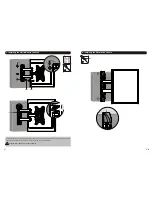
1b. For Solid Brick and Concrete Mounting

Drill pilot holes

1

2

Tighten both screws 

leaving a 3mm space 

from the wall.

WARNING

• Make sure that mounting screws are anchored into the center of the studs. The use of a stud 
  finder is highly recommended. 

• Installers must verify that the supporting surface will safely support the combined weight of the 
  equipment and all attached hardware and components.

60mm

(

2.4"

)

60mm

(

2.4"

)

ø 10mm

(

ø 3/8"

Mark the

exact location of

mounting holes

1a. For Wood Stud Wall Mounting

2

1

Drill pilot holes

3

Tighten both screws 

leaving a 3mm space 

from the wall.

X

X

ø 4

.

5mm

(

ø 3/16"

55mm

(

2.2"

)

55mm

(

2.2"

)

Find and mark the

exact location of

mounting holes

W-A

W-B

3mm

3mm

W-A

X

A

With the arrows 
pointing up

With the arrows 
pointing up

Summary of Contents for A2007

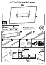
Page 1: ...on LED LCD TV Wall Mount 42 MAX CAUTION DO NOT EXCEED RATED LISTED WEIGHT SERIOUS INJURY OR PROPERTY DAMAGE MAY OCCUR 75x75 100x100 200x100 200x200 A2007 20kg 44lbs RATED 20kg 44lbs RATED FOR CUSTOMER SERVICE CALL 855 449 8833 TUFF ...

Page 2: ...ed by someone with good mechanical ability who has basic building experience and fully understands this manual Make sure that the supporting surface will safely support the combined weight of the equipment and all attached hardware and components If mounting to wood wall studs make sure that mounting screws are anchored into the center of the studs The use of a stud finder is highly recommended Al...

Page 3: ...the studs The use of a stud finder is highly recommended Installers must verify that the supporting surface will safely support the combined weight of the equipment and all attached hardware and components 60mm 2 4 60mm 2 4 ø 10mm ø 3 8 Mark the exact location of mounting holes 1a For Wood Stud Wall Mounting 2 1 Drill pilot holes 3 Tighten both screws leaving a 3mm space from the wall X X ø 4 5mm ...

Page 4: ... For Recessed Back Screens or to Access A V Inputs Tighten all screws but do not over tighten Screw the VESA plate onto the TV Note Choose the appropriate screws and spacers if necessary according to the type of screen TV TV TV M E M F M I M K M E M F M I M L M G M H M J M L M G M H M L M K M J ...

Page 5: ...all mount attached the TV Align the holes in the wall plate with the screw heads on the wall and lower the wall plate Then install the remaining screw through the washer W A W C 4 Installing the Decorative Covers B Tighten all screws but do not over tighten ...

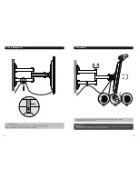
Page 6: ...in the cables for cantilever arm movement C Adjust to the desired position or tilt Maintenance Check that the bracket is secure and safe to use at regular intervals at least every three months Please contact your distributor if you have any questions Loosen the knob to adjust the TV to the desired angle then tighten the knob to secure 180 20 20 2 3 1 ...

Reviews: