background image


GENERAL ASSEMBLY 


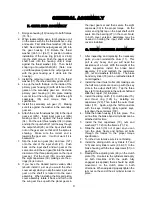
F. GEAR END ASSEMBLY 


1.  Bolt gear-housing (10) loosely into both frames 

(73, 74). 

2.  When reassembling use a lot of grease or oil 

on the areas such as the thrust washer, o-ring 
and seals.  First slide thrust washer (38) onto 
shaft.  Next install the output gear set (24) into 
the gear housing (10). Rotate the thrust 
washer ((24-5) or (24-7)) in position to allow 
installation of the snap ring ((24-8) or 24-9)) 
into the shaft groove. Push the gear set and 
shaft back into the housing until it stops 
against the thrust washer (38).  Then install 
snap ring onto output shaft (20).  

(Note:  Line 

up all three planet gears in the output gear set 
with the gear housing as it starts into the 
housing).


3.  Install the output sun gear (8, 111), the thrust 

washer (37), then the secondary gear set (23).   

4.  Line up the teeth that are on the inside of the 

primary gear housing (9) with all three of the 
gears on the secondary gear set.  Push the 
primary gear housing (9) into place making 
sure not to cut the o-ring (36).   Install the eight 
capscrews (35) and torque them to 
specification. 

5.  Install the secondary sun gear (7).  Making 

sure it is against the washer in the secondary 
gear set.  

6.  Attach the inner thrust washer (34) to the input 

gear set (22A).  Insert input gear set (22A) 
making sure it is against the thrust washer 
(34).  Put the outer thrust washer (34) in place 
and slip the input shaft (21) all the way though 
the output shaft (20). Let the input shaft stick 
out on the gear end so that all of the spline is 
showing.  Make sure the correct end is 
towards the gear end.   It will not work if it is 
backwards. 

7.  Slip the input sun gear (6A) and race (127) 

onto the end of the input shaft (21).  Push 
back on the input shaft and sun gear at the 
same time until the sun gear fits into the inside 
diameter of the three planet gears on the input 
gear set.  Put the cover (3A) on and secure 
the eight capscrews (30) making sure the o-
rings (33) is not cut.  

8.  If you have the blocked piston version, after 

rebuild, install it just as you would the other 
cover except when you slip the outer input sun 
gear on the shaft it is locked into the cover 
assembly.  When installing the blocked piston 
cover assembly rotate it back and forth until 
the sun gear lines up with the planet gears in 

the input gear set and then secure the eight 
capscews (30) to the proper torque.  On the 
motor end, lightly tap on the input shaft until it 
seats into the bearing (27) in the cover. Note:   
In both cover versions assistance may be 
needed in holding the input shaft while the 
cover is installed.  


G. DRUM SECTION ASSEMBLY 


1.  After inspecting and replacing the necessary 

parts, you can reinstall the drum (11).  This 
part is very heavy and you will need the 
assistance of a hoist.  With the weight of the 
drum supported, install the brake band 
assembly (77) and reattach the capscrews 
(91), nut and washers (85 & 86).   The brake 
band air cylinder (76) can be reattached later if 
not all together. 

2.  Install the inner thrust collar (46) making sure 

the half moon slots are lined up with the key 
slots in the output shaft (20).  Tap the three 
keys (47) into their slots in the output shaft and 
slide the coupler (12) into place. 

3.  Install the sliding clutch (13), clutch plate (15), 

and thrust ring (128) by installing six 
capscrews (129). Then install the outer thrust 
collar (131).  Again, align the half moon slots 
with the keys. Holding tightly against keys, 
lock down the set screws (130). 

4.  Slide the brake housing (16) into place.  The 

air line from the brake band air cylinder can be 
attached at this time.   

5.  Install the four capscrews (70), nuts and 

washers (71, 72) into the frames (73, 74). 

6.  Slide the clutch (13) out of gear so you can 

turn the drum freely and tighten all bolts 
through the frames to the proper torque 
specification. 

7.  Turn the drum to make sure it is not binding. 
8.  Install the sliding clutch air cylinders (17 and 

125) and air cylinder covers (96 & 97) to the 
brake housing with the four capscrews (51) on 
each side.   

9.  Readjust the adjusting nuts (99) on the clutch 

plate (15).  Hook air to the cylinders and apply 
air both directions. With the clutch fully 
engaged (air applied) there should be slight 
movement on the clutch plate in both 
directions.  When adjusted properly tighten the 
jam nut on the end of the air cylinder to lock in 
place. 

Summary of Contents for Rufnek 100

Page 1: ...BLY 6 E PLANET SET DISASSEMBLY 7 BLOCKED PISTON COVER DISASSEMBLY 8 BLOCKED PISTON COVER ASSEMBLY 8 GENERAL ASSEMBLY 9 F GEAR END ASSEMBLY 9 G DRUM SECTION ASSEMBLY 9 H BRAKE SECTION ASSEMBLY 10 TROUB...

Page 2: ...IC MODEL RN60 RN100 LEFT RIGHT MOUNT SPOOL OVER UNDER DRUM MOTOR TYPE 1 SINGLE SPEED GEAR MOTOR 2 TWO SPEED GEAR MOTOR 3 SINGLE SPEED GEROLER 4 TWO SPEED GEROLER 5 PISTON 6 VANE X NO MOTOR MANUAL TWO...

Page 3: ...t including the winch and cable is maintained properly 5 Avoid shock loads This type of load imposes a strain on the winch many times the actual weight of the load and can cause failure of the cable o...

Page 4: ...cated on drum barrel and clutch 4 Complete teardowns and component inspections Again severity and frequency of use will determine how often this should be done If the equipment that this winch is moun...

Page 5: ...the two holes in the top of the piston and run in evenly until the piston is clear of the housing An alternate way of removing the piston is to use a portable hydraulic power unit or air to gently pr...

Page 6: ...capscrews 45 If you replace the clutch make sure to torque the capscrews to the specified torque upon re assembly D GEAR SECTION DISASSEMBLY 1 Drain the oil at the bottom of the gear housing by remov...

Page 7: ...7...

Page 8: ...piston assembly and the piston 4B is not in use You may want to leave the piston and spacer 108B in the housing and bypass inspection 3 Remove the thrust washer 75B and sun gear 6B BLOCKED PISTON COVE...

Page 9: ...you slip the outer input sun gear on the shaft it is locked into the cover assembly When installing the blocked piston cover assembly rotate it back and forth until the sun gear lines up with the plan...

Page 10: ...until it is seated making sure not to damage the o rings or back up rings 5 Install the springs into the spring pockets If working in a horizontal position coat the 6 bottom of each spring with chass...

Page 11: ...OLUTION a Relief valve setting may be too low to allow proper lifting Increase relief valve pressure setting Note do not exceed recommended system pressures b Load being lifted may be more than the wi...

Page 12: ...E COVER 19 43032 2 BUSHING 20 42976 1 OUTPUT SHAFT 21A 43161 1 INPUT SHAFT 21B 42977 1 INPUT SHAFT 22A 4249 1 INPUT GEAR SET 22B 4237 1 INPUT GEAR SET 23 4235 1 SECONDARY GEAR SET 24 4236 1 OUTPUT GEA...

Page 13: ...42929 1 BRAKE AIR CYLINDER 77 4238 1 BRAKE BAND ASSY 79 42029 1 BLOCK C B 80B 42030 1 HOSE ASSY 81B 42259 1 LONG MALE ELBOW 82 42438 2 FITTING TEE 83 41838 2 STRAIGHT ADAPTER 84 42089 3 ELBOW 85 2052...

Page 14: ...122 40280 1 STRAIGHT ADAPTER 123 43459 1 HOSE 124 42866 1 ZERK GREASE 125 43578 1 AIR CYL W SWITCH 127 43289 1 SPACER INPUT 128 43257 1 RING THRUST 129 31550 1 SCREW FLAT 130 20515 2 SET SCREW 131 436...

Page 15: ...19 42868 2 BUSHING 20 42869 1 OUTPUT SHAFT 21A 43123 1 INPUT SHAFT 21B 42870 1 INPUT SHAFT 22A 4250 1 INPUT GEAR SET 22B 4228 1 INPUT GEAR SET 23 4229 1 SECONDARY GEAR SET 24 4230 1 OUTPUT GEAR SET 25...

Page 16: ...945 1 R H FRAME 75B 42949 1 THRUST WASHER 76 42929 1 BRAKE AIR CYLINDER 77 4231 1 BRAKE BAND ASSY 79 42029 1 C B BLOCK 80B 42495 1 HOSE ASSY 81 42259 1 LONG MALE ELBOW 82 42438 2 FITTING TEE 83 41838...

Page 17: ...K MANIFOLD 121 42033 1 TEE SWIVEL 122 40280 1 ADAPTER STRAIGHT 123 43459 1 HOSE ASS Y 124 42866 1 GREASE ZERK 125 43578 1 AIR CYL W SWITCH 127 43288 1 SPACER 128 43505 1 RING THRUST 129 31550 6 CAPSCR...

Page 18: ...49 9 SNAP RING 1 27011 81574 item 23 A and B SA 4235 ITEM DESCRIPTION QTY PART NO 1 SECONDARY CARRIER 1 43013 2 SECONDARY PLANET GEAR 3 43014 3 BEARING 6 30484 4 RETAINING RING 3 41715 5 PLANET PIN 3...

Page 19: ...7 3 NEEDLE BEARING 3 30484 4 RETAINING RING 3 41715 5 PLANET PIN 3 42950 6 THRUST WASHER 6 40264 7 PLATE 1 42954 81575 item 23 A and B SA 4229 ITEM DESCRIPTION QTY PART 1 SECONDARY CARRIER 1 42926 2 S...

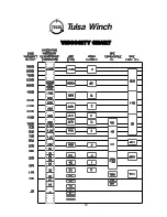
Page 20: ...19 VISCOSITY CHART...

Page 21: ...48 54 7 16 14 20 54 62 65 73 63 71 76 84 1 2 13 20 80 90 100 110 100 110 120 130 9 16 12 18 105 115 125 135 125 135 150 160 5 8 11 18 170 180 195 205 200 210 230 240 3 4 10 16 285 295 340 350 330 340...

Page 22: ...21 TWG PO Box 1130 Jenks OK 74037 1130 USA Phone 918 298 8300 www dovertwg com...

Reviews: