15
DISASSEMBLY
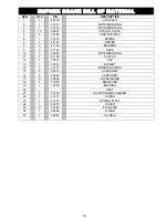
GEARBOX DISASSEMBLY
1. Supporting the end of the output
shaft (68) with a hoist, remove the
housing cover (76) by removing
capscrews (3 & 46), nuts (20 & 24),
and washers (19 & 23).
2. Use the hoist to lift the output shaft
(68), bushings (69), keys (70), and
gear (assembled items 26, 30, 71,
72, 73, 74, and 75) out of the
housing (61).
3. Remove the bushings (69) from the
output shaft (68).
4. Remove the gear (75) from the
carriers (72) by removing the twelve
capscrews (71), nuts (26), and
washers (30), then pull the carrier
(72) off of the shaft (68). Finally,
remove the spacer (73), carrier (72),
and keys (70).
5. Remove the worm (57) from the
housing by removing either the motor
(90) and motor adapter (95) or the
end cap (51), depending on type of
drive. From the brake end, push the
worm (57) out of the housing (61).
Remove the bearings (54).
If the brake has not been removed,
see brake disassembly on pages
10-13 of this manual.
6. Inspect parts as follows, replacing
them if necessary:
A.
Inspect the carriers (72) for
damage.
B.
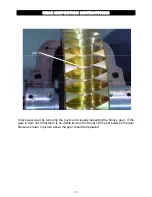
Inspect the gear (75) for
excessive wear or damage. See
page 16 for detailed instructions.
C.
Inspect the keys (70) and
bushings (69) for damage.
D.
Inspect the worm (57) for
excessive wear or signs of heat
checking or cracks.
E. Inspect the bearings (54) and
seals (55) for excessive wear or
damage.


