8
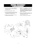
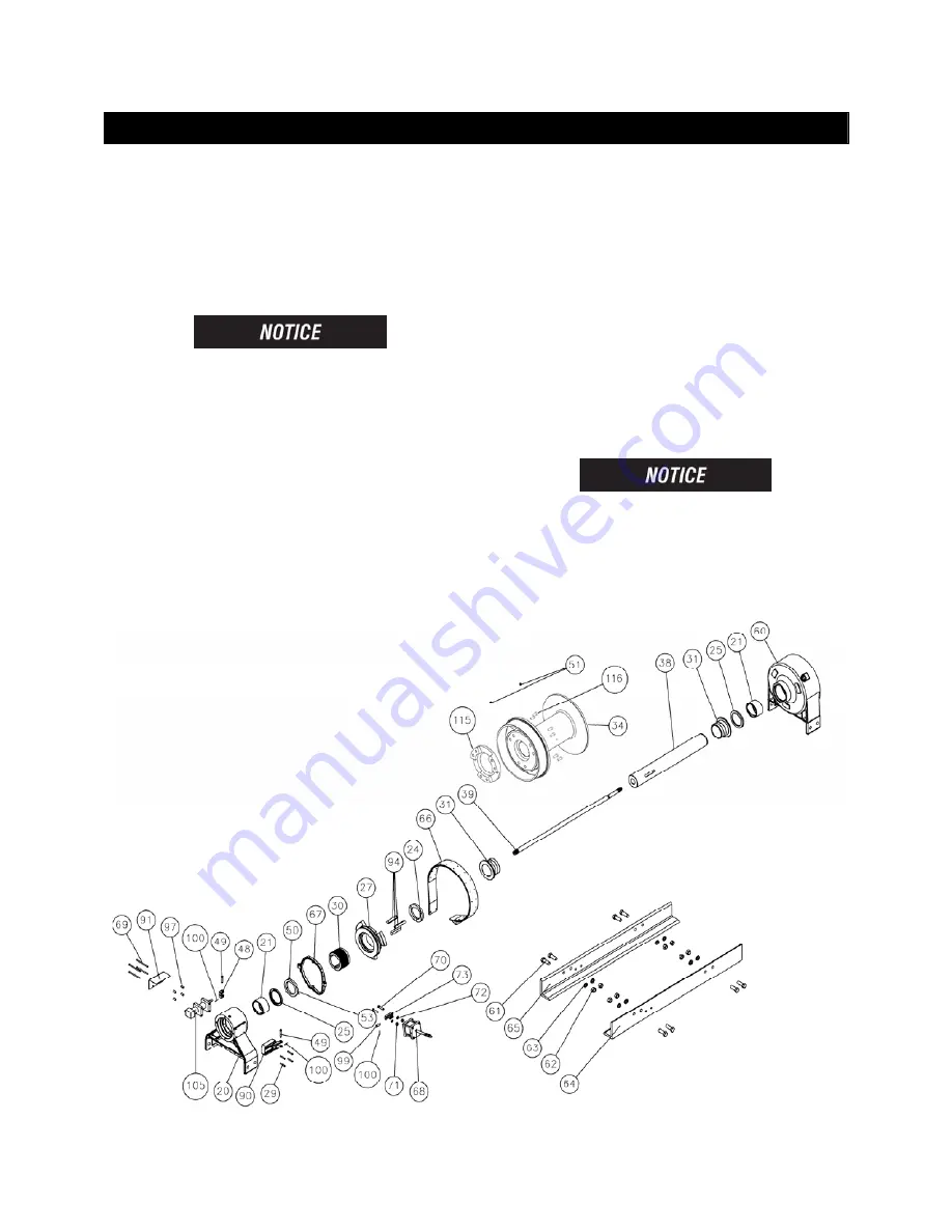
C. DRUM SECTION DISASSEMBLY
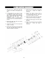
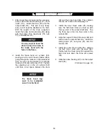
1. With the motor and brake disassembled, first
remove the cotter keys (100) and clevis pins
(49) connecting the yoke (67) to the bracket
(90) & air cylinder (105). Second, remove
the eight cap screws (29 & 69), four spacers
(97), air cylinder cover (91), air cylinder
(105), and bracket (90).
You may need to remove the
air lines, so it’s a good idea to
mark them for re-assembly.
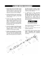
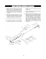
2. Support the weight of the drum with a hoist.
Remove the four cap screws (61) along with
the nuts and washers (63, 62) on the bottom
of the brake housing (20). Disconnect the
airline running from the air cylinder (68) to
the brake housing (20). Remove the brake
housing by sliding the housing off the output
shaft (38).
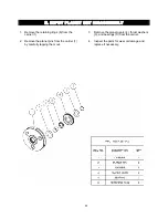
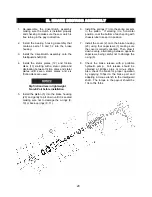
Remove the brake band assembly (66) by
removing two cap screws (70), nuts and
washers (71, 72) from the frames (64 or 65).
Note which frame the mounting bolts are on
for re-assembly. Inspect and replace if
needed.
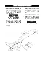
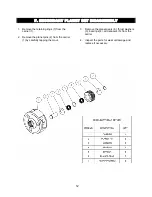
3. Remove the outer thrust collar (53) by
loosening the three set screws (50).
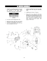
4. Remove the yoke (67), sliding clutch (27),
and coupler (30). Remove the three keys
(94) and the inner thrust collar (24).
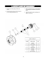
Remove the drum using a hoist. Inspect the
bushings (31) in both ends of the drum.
You should also inspect the bushing
and seal (21, 25) that are located
in the end of the brake housing.
Summary of Contents for Rufnek Intelliguard 80
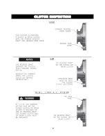
Page 9: ...9 CLUTCH INSPECTION ...
Page 26: ...26 VISCOSITY CHART ...


