Page 5 of 8
MAINTENANCE
Important
: All maintenance operations must be carried out by qualified personnel, who should read and understand the instruc-
tions reproduced in this booklet.
Important
: Before carrying out any operation, turn the power supply off.
Important
: Any burns or overheating phenomena indicate an anomalous operating condition. In such cases, immediately inves-
tigate to find the root cause of the problem in order to avoid affecting other components. In normal operating con-
ditions the components are warm, but never hot.
Unidirectional feeders do not require special maintenance operations.
It
’
s only necessary to clean the following items on a regular basis:
- Clean the
air gap
, removing all metal particles, that may alter the natural vibration frequency.
To carry out these operations, do not use liquids, only use compressed air and a clean cloth.
•
After washing and de-greasing the
channel
, check it to evaluate its roughness. After prolonged operation the roughness
may be reduced, and consequently the parts to be fed would have a lesser degree of adhesion. To restore the original
roughness level, simply carry out a light grinding or glazing operation.
•
After these operations, it may be necessary to repeat the calibration procedure.
CALIBRATION
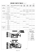
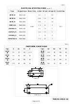
To calibrate the vibrator, check whether the air gap dimensions comply with what is specified in Table 3, then adjust the thrust
exerted by the leaf springs by changing the number of laminations in each set.
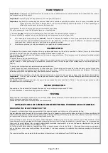
The air gap is the gap between the magnet and the counter-magnet surfaces. This clearance must be adjusted to obtain suitable
operating conditions.
To adjust the air gap, proceed as follow:
- Loosen screws V and slide in a shim as wide as the required air gap, move the magnet nearer to the counter-magnet, then
tighten screws V. While performing this operation, make sure that the final air gap width corresponds to the value specified in
Table 3.
To carry out a further feed rate adjustment proceed as follows :
- Slowly loosen the lower fastening screws on a leaf spring set. This should vary the speed at which the parts are fed through the
channel. If the speed decreases, add a leaf spring - a set at a time - until the required performances are obtained. If the speed
increases, proceed in the opposite way, and remove some leaf springs.
In normal operating conditions, the vibrator does not produce any noise. In case you hear a bang, stop the vibrator immediately.
Important
: If the air gap is too thin, the magnet and counter-magnet may touch, thereby damaging each other and producing
a deep metallic sound.
Conversely, if the air gap is too wide, the power input exceeds the value specified in Table 3, the coil may get burned and the
vibration control circuit damaged.
NOISE EMISSIONS
Depending on the materials fed through the channel, noise emissions may exceed 75 DbA.
In such conditions, a sound-proofing system is required.
TESTING
Both standard and custom-made units are carefully tested before shipment. Custom-made devices are checked for compliance
with the features specified in the contract.
Standard units are checked for compliance to our standards.
APPLICATIONS OF LINEAR UNIDIRECTIONAL FEEDERS AND CHANNELS
CHOOSING THE RIGHT VIBRATOR TYPE
In general, a vibrator type is chosen according to the channel length, and to the size of the parts to be fed.
Special attention must be paid to the conveyor channel and its support, which must be heavy and rigid. In these conditions the
channel itself can vibrate without causing anomalous vibrations that may affect the operation of the vibrator. To achieve this aim,
we recommend following the drawing and specifications carefully.
If the vibrating channel is to be very short, linear unbalanced vibrators may also be used, such as type CHTR 40-50-70. These
types however, are not equipped with vibration-damping devices, since the base functions as a reaction mass. As a consequence,
they must be rigidly fastened to a support with suitable dimensions and weight, so as not to disperse vibrations to the ground,
thereby reducing the efficiency of the vibrator itself.
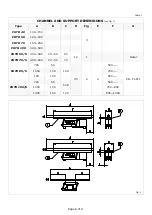
As for the overall dimensions and applications of the channels, please refer to the Table 1. Obviously these values were worked
out on the basis of average configurations. Nevertheless, it is always necessary to calibrate the vibrator according to the above
procedure.
The required profiles can be made by the customers themselves, or be obtained from TUMAC warehouses.
Summary of Contents for CHTR 40
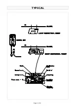
Page 3: ...Page 3 of 8 TYPICAL...

