91
ELECTRONIC CONTROLLER INSTRUCTION
5-2. FUNCTION TABLE
No
Control Function Control Objects
Contents
Remark
1
Initial
Buzzer
Operation
Fan
Lamp
88 LED
2
Temperature
Compressor
Control
Evap-Fan Motor
Con-Fan Motor
LED
3
Turbo
Compressor
Freeze
Evap-Fan Motor
Con-Fan Motor
LED
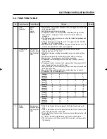
1. Buzzer will be ring within 2 seconds when you plugged-in and turned
on the power switch.
2. 88 LED displays inside temperature.
3. Compressor will be run if evaporator's temperature is higher than
38.3˚F(3.5˚C), compressor will not run for 3 minutes when you
plugged-in.
4. The fluorescent lamp will come on, when the inside temperature has
reached 23˚F(-5˚C).
5. If inside temperature is lower than -50˚F or higher than 50, 88 LED
displays 'Lo' or 'Hi' respectively.
6. Evap. Fan Motor will be run if D-sensor sense lower than 14˚F or 10
minutes has passed from when you plugged-in.
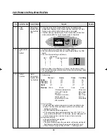
1. By pushing up/down button, you can set the desired inside
temperature from '5˚F' to '-17˚F'.
2. 88 LED will display a setting temperature, when you push up/down
button.
3. 88 LED will indicate real inside temperature, after your setting.
4. Buzzer rings 1 time whenever each button is pressed.
5. Compressor automatically turns on and off by F-sensor (Except
error mode)
6. Compressor will not come on for 3 minutes After Compressor is Off,
even though the F-sensor is at On point.
7. Evap. Fan Motor runs continuously except when door is opened and
during defrost mode.
8. Evap. Fan Motor will start within 3 seconds when door is closed.
9. Compressor On/off temperature(˚F)
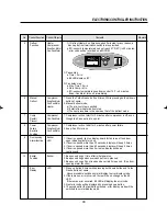
1. If the Turbo Freeze button is pressed, the Turbo freeze mode will
start.
2. If the Turbo Freeze button is pressed during the Turbo Freeze mode,
the Turbo Freeze mode is canceled.
3. During the Turbo Freeze mode, the temperature up/down button will
not operate.
4. T.F lamp in 88 LED is lighted during the Turbo Freeze mode.
5. The compressor and Condenser-Fan Motor operate continuously for
120 minutes.
Setting
Comp On
Comp Off
Setting
Comp On
Comp Off
Setting
Comp On
Comp Off
Setting
Comp On
Comp Off
Setting
Comp On
Comp Off
5
9
1
0
4
-4
-5
-1
-9
-10
-6
-14
-15
-11
-19
4
8
0
-1
3
-5
-6
-2
-10
-11
-7
-15
-16
-12
-20
3
7
-1
-2
2
-6
-7
-3
-11
-12
-8
-16
-17
-13
-21
2
6
-2
-3
1
-7
-8
-4
-12
-13
-9
-17
1
5
-3
-4
0
-8
-9
-5
-13
-14
-10
-18
Summary of Contents for TGF-13F
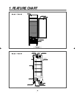
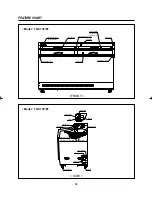
Page 11: ...8 Model TGM 5R FEATURE CHART DOOR HANDLE CONDENSER LEVELING LEG SIDE...
Page 13: ...10 WIRING DIAGRAM Model TGM 35R Model TGM 45R 3 4...
Page 14: ...11 WIRING DIAGRAM Model TGM 33R F L Lamp 17W 3 4 F L Lamp 17W Model TGM 22R...
Page 20: ...17 5 TROUBLE SHOOTING CHART 1 THE REFRIGERATOR DOES NOT COOLING...
Page 21: ...18 TROUBLE SHOOTING CHART 2 THE REFRIGERATOR DOES NOT COOLING WELL...
Page 22: ...19 TROUBLE SHOOTING CHART 3 LAMP DOES NOT LIGHT WELL...
Page 23: ...20 TROUBLE SHOOTING CHART 4 WHEN THERE IS A EXCESSIVE NOISE...
Page 25: ...22 PARTS DIAGRAM 2 COMPRESSOR PARTS Model TGM 69R 48R 45R 35R 33R...
Page 26: ...23 PARTS DIAGRAM Model TGM 22R...
Page 27: ...24 PARTS DIAGRAM Model TGM 14R 11R...
Page 28: ...25 PARTS DIAGRAM Model TGM 5R...
Page 30: ...27 PARTS DIAGRAM Model TGM 48R 45R 35R 33R...
Page 31: ...28 PARTS DIAGRAM Model TGM 22R 14R 11R...
Page 32: ...29 PARTS DIAGRAM Model TGM 5R...
Page 33: ...30 PARTS DIAGRAM 4 EVAPORATOR PARTS Model TGM 48R 35R...
Page 34: ...31 PARTS DIAGRAM Model TGM 69R 45R 33R...
Page 35: ...32 PARTS DIAGRAM Model TGM 22R...
Page 36: ...33 PARTS DIAGRAM Model TGM 14R...
Page 38: ...35 PARTS DIAGRAM Model TGM 5R...
Page 39: ...36 PARTS DIAGRAM 5 LIGHTING PARTS Model TGM 48R 35R 22R...
Page 41: ...38 PARTS DIAGRAM Model TGM 14R...
Page 42: ...39 PARTS DIAGRAM Model TGM 11R 5R...
Page 43: ...40 PARTS DIAGRAM 6 SHELF PARTS Model TGM 69R 48R 35R...
Page 44: ...41 PARTS DIAGRAM 7 ADVERTISING ADVERTISING FRAME PARTS Model TGM 69R 48R 35R...
Page 45: ...42 PARTS DIAGRAM Model TGM 45R 33R 22R 14R...
Page 46: ...43 PARTS DIAGRAM 8 GRILL PARTS Model TGM 69R 48R 45R 35R 33R Model TGM 22R Model TGM 14R 11R...
Page 57: ...54 3 Separate the Lamp Shield End Cap 4 Replace the Lamp REPLACEMENT OF MAIN COMPONENTS...
Page 82: ...Commercial Freezer Service Manual Model No TGF 23F TGF 13F TGF 9F...
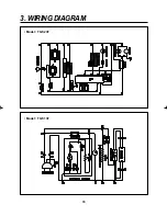
Page 88: ...86 3 WIRING DIAGRAM Model TGF 23F Model TGF 13F...
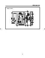
Page 89: ...87 WIRING DIAGRAM Model TGF 9F...
Page 108: ...VISION CREATIVE INC...

