93
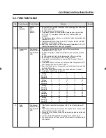
ELECTRONIC CONTROLLER INSTRUCTION
No
Control Function Control Objects
Contents
Remark
5
Defrost
Heater
Function
Compressor
Evap-Fan Motor
Con-Fan Motor
6
Manual
Compressor
Defrost
Evap-Fan Motor
Con-Fan Motor
Heater
7
Comp
Compressor
Restart
Con-Fan Motor
Prevent
8
Power
Compressor
Failure
Evap-Fan Motor
Back-Up
Con-Fan Motor
Function
9
Door opening
Buzzer
Alarm function
LED
10
Buzzer
Buzzer
Function
11
Error
LED
Display
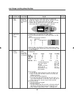
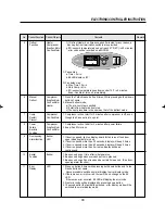
f. If Defrost Heater's on time exceeds 40 minutes for any reason, a
back-up defrost termination switch is also provided.
g. If D-sensor's temperature does not reach 47˚F(8˚C) in 40 minutes,
error code will be recorded on a MICOM.
C. Pause step
a. Time = 3 min.
b. 88 LED displays 'dF'
D. Fan delay step
a. Max. Time = 5 min
b. Only Comp. is On.
c. If D-sensor temperature goes down under 14˚F in 5 minutes,
Evap.-Fan Motor turns on immediately.
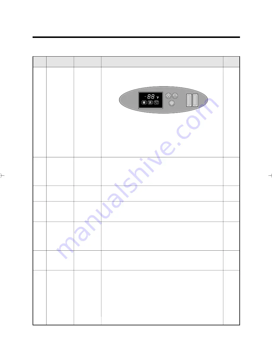
1. Press the Turbo Freeze button 5 times, While pressing both up/down
button at same.
2. Manual defrost mode.
a) The pre-cool step is omitted.
b) It starts from heater defrost step.
c) The next procedure is the same as that of the defrost mode.
1. Compressor will not start for 3 minutes after compressor is off, even
though the F-sensor is at on point.
1. Compressor will not strat for 3 minutes after power failure.
2. Evap.-Fan Motor is on.
1. If door is opened, light on display board for fan turns off and door
open indicating lamp turns on.
2. If door is opened more than 30 seconds, display will beep 3 times.
3. If door is opened more than 60 seconds, display will beep 5 times.
4. If door is opened more than 5 minutes, display will beep
continuously.
1. Beep sound rings 1 time after initial power on.
2. Beep sound rings whenever each button is pressed.
3. Beep sound rings if door is opened a certain time period. (See door
opening alarm function)
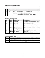
1. Press up button 5 times while pressing both down button and Turbo
Freeze button at same.
Above procedure switches normal display to error display mode.
2. If there was no error occurred, there will be no change on the 88
LED.
If there was error occurred, 88 LED will display the error code.
3. Next error code will be displayed by pressing down button.
4. 10 seconds after the last button pressed, error display mode will be
switched to normal display mode.
TEMPERATURE
TURBO FREEZE
Turbo air
Long Beach, CA
LAMP
POWER
T.F.
FAN
DOOR
Summary of Contents for TGF-13F
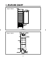
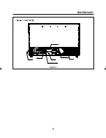
Page 11: ...8 Model TGM 5R FEATURE CHART DOOR HANDLE CONDENSER LEVELING LEG SIDE...
Page 13: ...10 WIRING DIAGRAM Model TGM 35R Model TGM 45R 3 4...
Page 14: ...11 WIRING DIAGRAM Model TGM 33R F L Lamp 17W 3 4 F L Lamp 17W Model TGM 22R...
Page 20: ...17 5 TROUBLE SHOOTING CHART 1 THE REFRIGERATOR DOES NOT COOLING...
Page 21: ...18 TROUBLE SHOOTING CHART 2 THE REFRIGERATOR DOES NOT COOLING WELL...
Page 22: ...19 TROUBLE SHOOTING CHART 3 LAMP DOES NOT LIGHT WELL...
Page 23: ...20 TROUBLE SHOOTING CHART 4 WHEN THERE IS A EXCESSIVE NOISE...
Page 25: ...22 PARTS DIAGRAM 2 COMPRESSOR PARTS Model TGM 69R 48R 45R 35R 33R...
Page 26: ...23 PARTS DIAGRAM Model TGM 22R...
Page 27: ...24 PARTS DIAGRAM Model TGM 14R 11R...
Page 28: ...25 PARTS DIAGRAM Model TGM 5R...
Page 30: ...27 PARTS DIAGRAM Model TGM 48R 45R 35R 33R...
Page 31: ...28 PARTS DIAGRAM Model TGM 22R 14R 11R...
Page 32: ...29 PARTS DIAGRAM Model TGM 5R...
Page 33: ...30 PARTS DIAGRAM 4 EVAPORATOR PARTS Model TGM 48R 35R...
Page 34: ...31 PARTS DIAGRAM Model TGM 69R 45R 33R...
Page 35: ...32 PARTS DIAGRAM Model TGM 22R...
Page 36: ...33 PARTS DIAGRAM Model TGM 14R...
Page 38: ...35 PARTS DIAGRAM Model TGM 5R...
Page 39: ...36 PARTS DIAGRAM 5 LIGHTING PARTS Model TGM 48R 35R 22R...
Page 41: ...38 PARTS DIAGRAM Model TGM 14R...
Page 42: ...39 PARTS DIAGRAM Model TGM 11R 5R...
Page 43: ...40 PARTS DIAGRAM 6 SHELF PARTS Model TGM 69R 48R 35R...
Page 44: ...41 PARTS DIAGRAM 7 ADVERTISING ADVERTISING FRAME PARTS Model TGM 69R 48R 35R...
Page 45: ...42 PARTS DIAGRAM Model TGM 45R 33R 22R 14R...
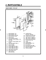
Page 46: ...43 PARTS DIAGRAM 8 GRILL PARTS Model TGM 69R 48R 45R 35R 33R Model TGM 22R Model TGM 14R 11R...
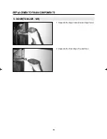
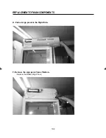
Page 57: ...54 3 Separate the Lamp Shield End Cap 4 Replace the Lamp REPLACEMENT OF MAIN COMPONENTS...
Page 82: ...Commercial Freezer Service Manual Model No TGF 23F TGF 13F TGF 9F...
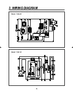
Page 88: ...86 3 WIRING DIAGRAM Model TGF 23F Model TGF 13F...
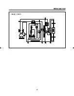
Page 89: ...87 WIRING DIAGRAM Model TGF 9F...
Page 108: ...VISION CREATIVE INC...

