94
ELECTRONIC CONTROLLER INSTRUCTION
No
Control Function Control Objects
Contents
Remark
12
Fuzzy
Heater
Deforst
Compressor
Evap-Fan Motor
Con-Fan Motor
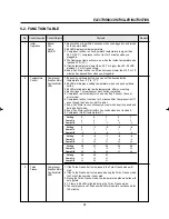
The Defrost step will be started at following conditions.
1. The compressor has run for 30 minutes.
2. There is no openning the door for 30 minutes.
3. The temperature of D-sensor is lower than 5˚F.
4. The temperature of F-sensor is higher than D-senser's temperature
by 53.6˚F for 10 minutes.
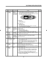
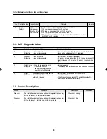
Code
Content
Perception Method
Freezer operation state
F1
F-sensor
- Sensor shorted
- The compressor runs for 30 minutes and rests for 5 minutes.
Malfunction
- Sensor disconnected
- Above action will repeat, until it is repaired.
D1
D-sensor
- Sensor shorted
- Defrost heater will attempt to defrost.
Malfunction
- Sensor disconnected
- If F-sensor temp. is higher than 28.4˚F then heater goes off.
- Heater turns on for 20 minutes, if F-sensor is in error mode
too.
C1
Cycle, Comp. - When the temperature of the
- Normal operation.
Malfunction
D-sensor is over 32˚F
(Compressor is automatically turned on and off by F-sensor.)
although the compressor has
been running for 30 minutes.
F3
Defrost
When the D-sensor temperature
- Defrost heater will be come on for 40 minutes
Malfunction
doesn't reach 47˚F
every time setted.
within 40 minutes.
- If the D-sensor's temp. reach 47˚F within 40 minutes, D-
heater will be turned off immediately.
5-3. Self - Diagnosis table
Sensor Operation
Description
Remarks
F-sensor
-Thermistor(Electrical resistance varies with temperature changing)
- Wire color is orange.
-Act like thermostat. Detects air temperature.
D-sensor
-Thermistor(Electrical resistance varies with temperature changing)
- Wire color is blue.
-Act like thermostat. Detects Evap. coil's temperature.
5-4. Sensor Description
Summary of Contents for TGF-13F
Page 11: ...8 Model TGM 5R FEATURE CHART DOOR HANDLE CONDENSER LEVELING LEG SIDE...
Page 13: ...10 WIRING DIAGRAM Model TGM 35R Model TGM 45R 3 4...
Page 14: ...11 WIRING DIAGRAM Model TGM 33R F L Lamp 17W 3 4 F L Lamp 17W Model TGM 22R...
Page 20: ...17 5 TROUBLE SHOOTING CHART 1 THE REFRIGERATOR DOES NOT COOLING...
Page 21: ...18 TROUBLE SHOOTING CHART 2 THE REFRIGERATOR DOES NOT COOLING WELL...
Page 22: ...19 TROUBLE SHOOTING CHART 3 LAMP DOES NOT LIGHT WELL...
Page 23: ...20 TROUBLE SHOOTING CHART 4 WHEN THERE IS A EXCESSIVE NOISE...
Page 25: ...22 PARTS DIAGRAM 2 COMPRESSOR PARTS Model TGM 69R 48R 45R 35R 33R...
Page 26: ...23 PARTS DIAGRAM Model TGM 22R...
Page 27: ...24 PARTS DIAGRAM Model TGM 14R 11R...
Page 28: ...25 PARTS DIAGRAM Model TGM 5R...
Page 30: ...27 PARTS DIAGRAM Model TGM 48R 45R 35R 33R...
Page 31: ...28 PARTS DIAGRAM Model TGM 22R 14R 11R...
Page 32: ...29 PARTS DIAGRAM Model TGM 5R...
Page 33: ...30 PARTS DIAGRAM 4 EVAPORATOR PARTS Model TGM 48R 35R...
Page 34: ...31 PARTS DIAGRAM Model TGM 69R 45R 33R...
Page 35: ...32 PARTS DIAGRAM Model TGM 22R...
Page 36: ...33 PARTS DIAGRAM Model TGM 14R...
Page 38: ...35 PARTS DIAGRAM Model TGM 5R...
Page 39: ...36 PARTS DIAGRAM 5 LIGHTING PARTS Model TGM 48R 35R 22R...
Page 41: ...38 PARTS DIAGRAM Model TGM 14R...
Page 42: ...39 PARTS DIAGRAM Model TGM 11R 5R...
Page 43: ...40 PARTS DIAGRAM 6 SHELF PARTS Model TGM 69R 48R 35R...
Page 44: ...41 PARTS DIAGRAM 7 ADVERTISING ADVERTISING FRAME PARTS Model TGM 69R 48R 35R...
Page 45: ...42 PARTS DIAGRAM Model TGM 45R 33R 22R 14R...
Page 46: ...43 PARTS DIAGRAM 8 GRILL PARTS Model TGM 69R 48R 45R 35R 33R Model TGM 22R Model TGM 14R 11R...
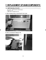
Page 57: ...54 3 Separate the Lamp Shield End Cap 4 Replace the Lamp REPLACEMENT OF MAIN COMPONENTS...
Page 82: ...Commercial Freezer Service Manual Model No TGF 23F TGF 13F TGF 9F...
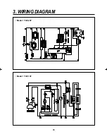
Page 88: ...86 3 WIRING DIAGRAM Model TGF 23F Model TGF 13F...
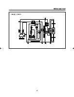
Page 89: ...87 WIRING DIAGRAM Model TGF 9F...
Page 108: ...VISION CREATIVE INC...

