background image


e-Boost-40/60 Instructions 


Page 5 

PART NUMBER 

FG-EBOOST-

40/60


2f. External Wastegate Connection


Most external wastegates share a similar design layout.   
Use the diagram to help identify the “top” and “bottom” port of your 
wastegate. 


-


When pressure is applied to the “bottom” port of a 
wastegate, i.e. underneath the wastegate diaphragm, it acts 
against the wastegate spring and the wastegate valve opens. 


-


When pressure is applied to the “top” port of a wastegate, 
i.e. above the wastegate diaphragm, its acts with the 
wastegate spring and helps to close the wastegate valve. 


There are two methods for connecting the e-Boost to an external wastegate. The method used depends on the following factors. 
 

-


The size of the spring fitted in your wastegate i.e. The boost pressure achieved by the wastegate spring only. 

-


The desired level of boost pressure and the difference between this and your wastegate spring pressure. 

-


The size of your turbocharger and wastegate and the resulting exhaust manifold backpressure in your system 

 
Turbosmart recommends using the “Two port” connection method (1) as a starting point.  If this connection method does not achieve the 
desired  boost pressure, fit a heavier wastegate spring to increase your minimum boost pressure, or use the next connection method. 
 

WARNING! 

Fitting a heavier wastegate spring may cause a higher than expected increase in boost pressure

.


Turbosmart recommends resetting the Boost Set Point values to Zero and measuring the new minimum boost pressure achieved by the new 
spring, before increasing your Boost Set Point values. 
 

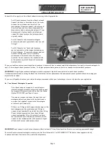
2g. “Two Port” Connection Method (1)


Connect the three ports on the e-Boost solenoid according to the diagram below.    
 

-


Port (1) Connects to a “boost only” pressure source, typically 
from the compressor housing on the turbocharger.  If your 
turbocharger does not have this fitting, connect to a “boost 
only” pressure source before the throttle-body or butterfly. 
Do not connect to the intake manifold, as the pressure signal 
will have both vacuum and boost pressure. 


-


Port (2) Connects to the “Top” port on the external wastegate. 
For Further information on external wastegate port 
identification see section 2f. 


-


Port (3) vents pressure from the e-Boost solenoid. Connect 
this hose to the intake side of the turbo, between the air 
cleaner and the inlet on the front of the turbocharger. 
Otherwise connect a short piece of the silicon hose and face 
the vent downwards to stop water or debris entering the 
solenoid. 


-


Connect the “Bottom” port on the external wastegate to the same “boost only” pressure source as Port (1) on the solenoid. For 
Further information on external wastegate port identification see section 2f. 


-


Use a tee-piece (not supplied) to share the “boost only” pressure source if necessary. 


If you are unable to achieve your desired boost pressure it is normally due to exhaust manifold backpressure forcing the wastegate valve open. 
To increase your boost pressure further, fit a heavier wastegate spring to increase your minimum boost pressure, or use the “Two Port” 
connection method (2) as below. 


Summary of Contents for e-Boost-40/60

Page 1: ...ort Connection Method 1 5 2h Two Port Connection Method 2 6 2i Multiple External Wastegate Connection 6 2j Wiring 7 3 BASIC OPERATION 7 3a Live Mode 7 3b Boost Pressure 7 3c Boost Parameters 7 3d User Parameters 8 3e Turning the e boost off 8 4 SETTING UP YOUR e BOOST 8 4a Over Boost Shutdown VERY IMPORTANT 8 4b e Boost Readout 9 4c Bar Graph 9 4d Setting Boost Pressure 9 4e Sensitivity 10 5 ADVAN...

Page 2: ... out our website at www turbosmart com au or your nearest Authorised Turbosmart Dealer for more information on Fuel Cut Defenders 2 INSTALLATION 2a Packing list e Boost 40 e Boost 60 Description Use 1 1 e Boost 1 1 e Boost solenoid Use in conjunction with e Boost 2 2 M3 Screws Secure e Boost solenoid 2 2 M3 Nylock nuts Secure e Boost solenoid 1 1 Wiring loom Connect e Boost to vehicle 1 1 Earth ey...

Page 3: ...essure vacuum signal from the inlet manifold Use the supplied tee piece if necessary Secure all connections with the supplied hose clamps 2c Installing the e Boost solenoid Mount the e Boost solenoid in an appropriate position in the engine bay with the screws supplied The e Boost solenoid is rated to a maximum temperature of 100 degrees Celsius 212 degrees Fahrenheit ensure that it is mounted a m...

Page 4: ... actuator may cause a higher than expected increase in boost pressure Turbosmart recommends resetting the Boost Set Point values to Zero and measure the new minimum boost pressure before increasing your Boost Set Point values If you are still unable to achieve your desired boost pressure ensure that your turbocharger is correctly sized for your application 2e Twin Internal Wastegate Connection The...

Page 5: ...et Point values to Zero and measuring the new minimum boost pressure achieved by the new spring before increasing your Boost Set Point values 2g Two Port Connection Method 1 Connect the three ports on the e Boost solenoid according to the diagram below Port 1 Connects to a boost only pressure source typically from the compressor housing on the turbocharger If your turbocharger does not have this f...

Page 6: ...he turbocharger If your turbocharger does not have this fitting connect to a boost only pressure source before the throttle body or butterfly Do not connect to the intake manifold as the pressure signal will have both vacuum and boost pressure Port 3 Connects to the Bottom port on the external wastegate For Further information on external wastegate port identification see section 2f If you are una...

Page 7: ...ys defaults to SP1 To change between the boost set points simply press the up or down arrow the set point will be displayed for one second and then the readout will return to Live boost or vacuum readings 3b Boost Pressure Boost pressures are set by entering a number in each of the three the boost set points see section 4d for more detail To view the boost set point value in Live Mode press the Mo...

Page 8: ...below indicates how the menu is structured in the e Boost Up or Down Arrows Hold the Mode button Hold the Mode button and press the Down arrow and press the Up Arrow Key SP1 SP2 SP3 Boost Set Point 1 2 3 GP1 GP2 GP3 Gate Pressure 1 2 3 SEN Sensitivity AU Auxiliary Output AL Audible Alarm BGR Bar Graph Scale OBS Over Boost Shutdown PSI KPA BAR Display Units ISP ESP Internal Set Point Switching Inte...

Page 9: ...e e Boost 60 is capable of controlling boost pressures up to a maximum of 4 08bar 60psi or 408kpa Boost pressure is determined by the boost set point value The boost set point value can be set from 0 to 99 and is not directly related to an actual boost pressure Boost pressure is set by increasing or decreasing the value of each of the three boost set points Increasing the boost set point will resu...

Page 10: ...the sensitivity value Press the Mode button momentarily and the sensitivity value will be stored Press the Mode button again to return to Live Mode Alternatively the sensitivity can be tuned live while editing this parameter Apply full load to the engine in a high gear at full throttle The Live boost pressure will be displayed on the readout Note the number that appears will be in bar psi or kpa d...

Page 11: ...croll to the AL parameter Press and hold the Mode button for two seconds press the up or down arrow to scroll to the desired pressure Note the number that appears in this parameter will be in bar psi or kpa depending on what has been set in the readout parameter see section 4b for more detail Press the Mode button momentarily and the alarm pressure will be stored Press the Mode button again to ret...

Page 12: ...tions Check to see if the e Boost solenoid is not blocked or contaminated with dirt oil build up or debris Check the joining hoses for splits cracks or loose connections and ensure they are not blocked kinked or restricted particularly if the existing hose was reused Pressure test the wastegate actuator for leakage the diaphragm or housing may be cracked or split Ensure the smooth and free operati...

Page 13: ...nties the quality of the products it designs and manufactures to be free of defects in material and workmanship This limited warranty is extended only to the original purchaser and may not be transferred or assigned This limited warranty applies to any product which after careful inspection by Turbosmart after receipt of the product from our authorized reseller is found to have a defect in either ...

Reviews: