


8
9
7
8
5
9
6
3
4.2 - DESCRIPTION OF THE MACHINE
Standard equipment:
• Protection frame for mechanical parts.
• Self-bearing frame with pneumatic wheels and
articulated draw-bar.
• Vibrating sieve with 8 mm mesh.
• Switch board built in accordance to EC norms.
•Piston pump with gravity ball valves.
•Mechanical gearbox with 2 speeds.
•Automatic mechanical safety device against
overpressure.
•Material recycling device
•Built-in air compressor of 270 l/m’ output.
•Positive action mixer of 180 l. (version MF).
•40 m (20+10 Ø 50 +10 Ø 40) of mortar rubber hoses
with cam-lock couplings.
•41 m (31 + 10) of air hose Ø 13 with quick couplings.
• Accessory box with spray gun and a series of nozzles.
• Technical literature.
Accessories upon request:
On line pressure gauge for hoses Ø 50.
Pumping nozzle for hoses Ø 40.
Pumping nozzle for hoses Ø 50.
Cement slurry injection device.
Hose extensions:
- Hose extensions of 10 m mortar/air (Ø 50 x 66 e Ø 13 x
19).
- Hose extensions of 20 m mortar/air (Ø 50 x 66 e Ø 13 x
19).
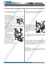
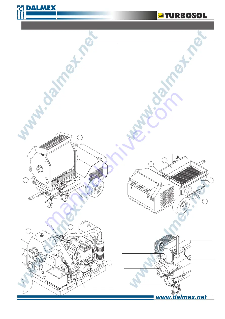
Main components:
The machine is made up primarily of:
a hopper (3) an agitator (4),
a piston pump group (5),
a diesel engine (6) that operates a gearbox (7) with 2
speeds (7a) a safety device (7b) against overpressure,
a compressor (8),
a vibrating sieve (9) operated by a mechanical gear-
box (10) and for the MF version: a fixed mixer (11).
4
11
9
10
ROD
ENGINE
STOP
7a
7b
BY
-
PASS
LEVER
MUSHROOM
SHAPED
LID
FOR
CYLINDER
SUCTION
COLLECTOR
INSPECTION
PLUG
FOR
THE
SUCTION
VALVE
INSPECTION
PLUG
FOR
THE
DELIVERY
VALVE
DELIVERY
OUTLET
WITH
PRESSURE
GAUGE
Summary of Contents for UNI 30 D
Page 4: ...4 ...


