44
TBV123 / TBV123-AN and TBV118L / TBV118L-AN Rigging Manual
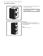
7.
If you are only adding one inverted TBV123 cabinet, then this completes
the procedure.
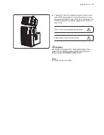
8.
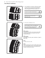
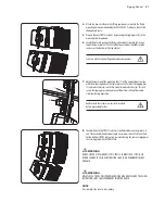
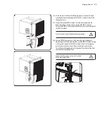
Carefully hoist and position the flybar/subwoofer/cabinet assembly until it is
on top of the prepared lower TBV123 cabinet. The feet of the upper TBV123
cabinet should fit into the recesses on top of the lower cabinet.
Take care not to trap your fingers between components.
9.
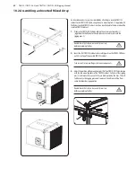
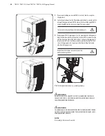
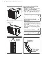
Remove upper TBV123 rigging pins(5) so the mounting links (6)drop down.
Adjust the position of the mounting links (6) of the TBV123 cabinet to align
with the mounting holes of the lower cabinet. Fully insert the rigging pins
(5) and rotate their arms until they are held in place by the clips. This will
secure the rigging pins and also prevent them from rattling from audio
vibrations during operation.
Double check that all pins are correctly inserted,
before proceeding further.
10.
This completes the mixed array assembly procedure.
!
!
WARNING
DO NOT EXCEED A TOTAL QUANTITY OF 1 TBV118L SUBWOOFER FOR 2 TBV123
CABINETS FOR 1 TBV123-FB FLYBAR. FAILURE TO FOLLOW INSTRUCTIONS MAY
CAUSE PERMANENT INJURY OR DEATH.
!
!
WARNING
THIS ARRAY SHALL ONLY BE MADE WITH THE TBV118L SUBWOOFER ON TOP, AND
THE TBV123 CABINETS BELOW. FAILURE TO FOLLOW INSTRUCTIONS MAY CAUSE
PERMANENT INJURY OR DEATH.
NOTE
Disassembly is the reverse of assembly.
5
6
5
6
Summary of Contents for TBV118L-AN
Page 50: ......

