background image

Over 30 subsidiaries and over

60 representations worldwide!

www.turck.com

100021277 | 2021/05

100021277

Summary of Contents for TN-IOL2 Series

Page 1: ...Your Global Automation Partner Instructions for Use TN IOL2 HF Read Write Heads...

Page 2: ...2 Hans Turck GmbH Co KG T 49 208 4952 0 F 49 208 4952 264 more turck com www turck com...

Page 3: ...mode 10 4 4 2 SIO mode standard I O mode 10 4 4 3 RSSI value output 10 4 4 4 Password function 10 4 5 Technical accessories 10 5 Installing 11 5 1 Installing cylindrical devices 11 5 2 Installing rect...

Page 4: ...e 21 9 3 RFID commands flow charts 22 9 3 1 Selecting an RFID command 22 9 3 2 Idle 22 9 3 3 Auto read 23 9 3 4 Auto write 24 9 3 5 Read 25 9 3 6 Write 27 9 3 7 Querying a UID and time stamp 29 9 4 Us...

Page 5: ...ath or severe in jury if not avoided CAUTION CAUTION indicates a dangerous situation of medium risk which may result in minor or moderate injury if not avoided NOTICE NOTICE indicates a situation whic...

Page 6: ...h threaded barrel devices n Quick Start Guide 2 3 Legal requirements The devices are subject to the following EU directives n 2014 30 EU electromagnetic compatibility n 2011 65 EU RoHS Directive n 201...

Page 7: ...ge with tags within the HF RFID system It is only possible to connect to and oper ate the devices via IO Link masters corresponding to specification V1 1 The devices may only be used as described in t...

Page 8: ...h a metal bodied M12 male connector plug for connecting the cable 4 1 Device overview M18 x 1 24 4 8 10 63 5 M12 x 1 8 13 5 LED 16 4 M30 x 1 5 36 5 10 63 5 M12 x 1 8 8 13 5 27 5 LED Fig 1 TN M18 Fig 2...

Page 9: ...mber of Turck tags This requires the read write head and the tag to operate in the same frequency range Depending on the power and frequency used the device ranges vary from a few millimeters up to se...

Page 10: ...the read write head The RSSI value is not output as a physical value but as a value on a scale from 0 7 The RSSI value does not have a linear characteristic in relation to the read write distance An R...

Page 11: ...ces fully protrudes from the surrounding area Observe the minimum distances between read write heads Fig 5 Mounting distances a b c d M18 30 mm 54 mm 60 mm 10 mm M30 45 mm 90 mm 90 mm 10 mm Avoid meta...

Page 12: ...es so that the front cap of the devices fully protrudes from the surrounding area Observe the minimum distances between read write heads Fig 6 Mounting distances Avoid metal in the proximity of the re...

Page 13: ...4 4T 2 TXL ID 6625503 to an IO Link master Connect the connecting cable coupling to the connector at the rear of the device 6 1 Wiring diagram Pin assignment Wiring diagram Description 4 3 1 2 L C Q1...

Page 14: ...k communication will start automat ically To do this the IO Link master sends a wake up request to the device 7 1 Initiating IO Link mode Set the cycle time on the IO Link master a The device is ready...

Page 15: ...ion range n Type of the alarm outputs time triggered or RSSI triggered n Password More information on setting the device via IO Link is provided in the IO Link parameter manual 8 2 Setting with IO Lin...

Page 16: ...ting Setting with IO Link function block 16 Hans Turck GmbH Co KG T 49 208 4952 0 F 49 208 4952 264 more turck com www turck com Function block for TIA Portal V14 Fig 8 Function block for TIA Portal V...

Page 17: ...g within the detection range 1 Tag present at read write head ANT 0 RF field switched off 1 RF field switched on ERROR CODE See list of error codes ALR2 0 Alarm 2 off 1 Alarm 2 on ALR1 0 Alarm 1 off 1...

Page 18: ...0 or 1 Idle N_ANT 0 Switch on RF field 1 Switch off RF field CMD 0 No command 1 Automatic read 2 Automatic write 3 Read 4 Write 5 Display UID and time stamp NB BLOCK Number of memory blocks to be read...

Page 19: ...ending on the sup ported command set of the used tag 2 0x02 FormatError 3 0x03 OptionNotSupported 5 0x05 CommandProblem 6 0x06 CommTagError 15 0x0F TagError 16 0x10 NoMemoryBlock 18 0x12 BlockProtecte...

Page 20: ...read write head Position Meaning 1 Optimum detection range RSSI value within the set limit value 2 RSSI limit value 3 Limit of the detection range RSSI value outside the set limit value 4 Tag outside...

Page 21: ...Red Error detected POWER Green SIO mode active 9 2 LED indication TN M 9 2 1 LED indication IO Link mode Indication Meaning Green flashing 1 Hz IO Link mode active Yellow Tag within the optimum detect...

Page 22: ...r on IO Link Select CMD 1 POWER LED flashing 1 Hz Fig 10 Selecting an RFID command 9 3 2 Idle The read write head automatically executes an Inventory as soon as a tag is located in the de tection rang...

Page 23: ...resent Tag true Ready bit is automati cally toggling New RFID READ CMD is sent every time ready bit is toggling New RFID data available Device RDY Device RDY BUSY LED flashing 1 Hz BUSY LED off Device...

Page 24: ...enters the detection range NB BLOCK write ADD write RFID data write Tag present Tag true Ready bit is automati cally toggling New RFID WRITE CMD is sent every time ready bit is toggling New RFID data...

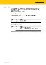
Page 25: ...the edge status of the START bit The RDY bit behaves as follows if during the command execution a tag is located in the detec tion range of the read write head START RDY Meaning 0 1 0 1 Input data pr...

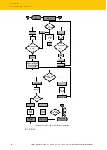
Page 26: ...will be send BUSY LED flashing 1 Hz Start bit toggled by user 0g1 1g0 No Yes BUSY LED flashing 1 Hz 1 New RFID data available Device RDY Device RDY BUSY LED flashing 1 Hz BUSY LED off Device is busy...

Page 27: ...as the edge status of the START bit The RDY bit behaves as follows if during the command execution a tag is located in the detec tion range of the read write head START RDY Meaning 0 1 0 1 Input data...

Page 28: ...ata available Device RDY Device RDY BUSY LED flashing 1 Hz BUSY LED off Device is busy Error ERR false ERR true ERROR LED on RFID error see error code list ERROR LED off RFID data written successfully...

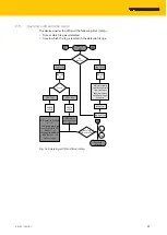
Page 29: ...tamp when tag was detected in PDI Bytes 13 21 IN range time MSB first in PDI Byte 22 30 Value is rising UID time stamp and IN range time from last tag is kept in memory until a new tag is detected 1 T...

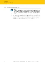
Page 30: ...interface must store the password on the tag Alternatively Turck can offer preconfigured tags on request Select the chip type of the tag used via the Mode parameter index 0x58 subindex 0x01 Set the d...

Page 31: ...irst check whether ambient interference is present If there is no ambient interference present check the connections of the device for faults If there are no faults there is a device malfunction In th...

Page 32: ...ed if it is faulty Observe our return acceptance conditions when returning the device to Turck 12 1 Returning devices Returns to Turck can only be accepted if the device has been equipped with a Decon...

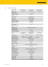
Page 33: ...flush Ambient temperature 25 80 C Design Threaded barrel M18 1 Threaded barrel M30 1 5 Rectangular Dimensions 63 5 mm 66 40 40 mm Housing diameter 18 mm 30 mm Housing material Metal CuZn chrome plate...

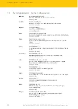
Page 34: ...S A S 11 rue de Courtalin Bat C Magny Le Hongre F 77703 MARNE LA VALLEE Cedex 4 www turckbanner fr Great Britain TURCK BANNER LIMITED Blenheim House Hurricane Way GB SS11 8YT Wickford Essex www turckb...

Page 35: ...w turck ru Sweden Turck Sweden Office Fabriksstr ket 9 433 76 Jonsered www turck se Singapore TURCK BANNER Singapore Pte Ltd 25 International Business Park 04 75 77 West Wing German Centre 609916 Sing...

Page 36: ...Over 30 subsidiaries and over 60 representations worldwide www turck com 100021277 2021 05 100021277...

Reviews: