background image

Operation

C.

Return the wand back to its holder.

Important:

Contact an Authorized Service

Dealer if the spreader-sprayer fails to operate
properly.

Cleaning the Sprayer

Clean the spray system after

each

spraying session.

Important:

Always empty and clean the sprayer

immediately after each use. Failure to do so may
cause the chemicals to dry or thicken in the lines,
clogging the pump and other components.

To properly clean the spray system:

Use three separate rinses.

Use a minimum of 5 gallons (19 L) for each rinse.

Use the cleaners and neutralizers as recommended
by the chemical manufacturers.

Use pure clean water (no cleaners or neutralizers)
for the

last

rinse.

WARNING

Do Not clean spray nozzles by mouth or blowing
through them. Swallowing or inhaling chemicals
could cause serious injury or death.

Replace all worn and damaged nozzles.

Make sure nozzles are installed correctly.

1.

Drive the machine to a designated cleaning area.

2.

Stop the spreader-sprayer on a level surface, leave
the motion control lever in the neutral position,
and turn off the engine. Engage the parking brake.

3.

Fill the tank with clean fresh water and close the
cover.

4.

Start the engine.

5.

With the motion control lever in neutral position,
engage the pump, and set the engine throttle to
“FAST”.

6.

Set the three spray valves to “ON”.

7.

Allow the water in the tank to spray out through
the nozzles.

8.

Check the nozzles to ensure that they are all
spraying correctly.

9.

Remove the wand from its holder and point it in a
safe direction.

10.

Squeeze the spray wand trigger to release the
pressure.

11.

Return the wand to its holder.

12.

Set the spray control levers to the “OFF” position,
disengage the pump, and stop the engine.

13.

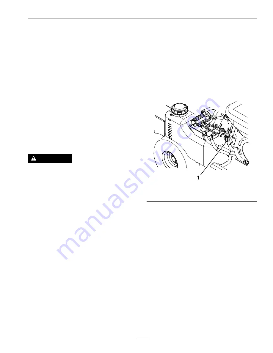
Clean the strainer located in front of the right
tank. Close the tank supply valve. When removing
the canister, drain any unused chemical from the
line and dispose of it according to local codes and
the chemical manufacturer's instructions.

Important:

If you used wetable powder

chemicals, clean the strainer after each tank
rinse.

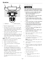
g314218

Figure 26

1.

Strainer

14.

Repeat steps through 13.

15.

Using a garden hose, spray off the outside of the
sprayer tank with clean water.

Note:

Do Not use a power washer to clean the

machine. The high pressure water may force
residual corrosive materials into spreader-spreader
components.

16.

Remove the nozzles and clean them by hand.
Replace damaged or worn nozzles.

17.

Allow the spreader-sprayer to completely dry
before the next use.

Calibrating the Sprayer Flow

Note:

Before using the sprayer for the first time,

change nozzles, or as needed–calibrate the sprayer
flow and speed.

Note:

Refer to the chemical product label for

application rate recommendations.

31


Summary of Contents for Z-SPRAY

Page 1: ...Operator s Manual For Serial Nos 406 294 345 Higher Part No 4504 922 Rev A Z SPRAY...

Page 2: ...vered or grass covered land unless the engine is equipped with a spark arrester as in Section 4442 maintained in effective working order or the engine is constructed equipped and maintained for the pr...

Page 3: ...training materials and Operator s manuals If additional information is needed or should you require trained mechanic service contact your authorized Z Turf Equipment dealer or distributor All Z Turf...

Page 4: ...44 Check Safety Interlock System 47 Check for Loose Hardware 48 Service Air Cleaner 48 Change Engine Oil 48 Check Hydraulic Oil and Tank Level 48 Change Hydraulic System Filter and Fluid 48 Check Tire...

Page 5: ...designed and tested this machine to offer reasonably safe service however failure to comply with safety instructions may result in injury or death Read understand and follow all instructions and warni...

Page 6: ...to expose the adhesive surface Apply only to a clean dry surface Smooth to remove any air bubbles Familiarize yourself with the following safety signs and instruction labels They are critical to the...

Page 7: ...ts decal135 6728 135 6728 1 Press and hold foot button to turn on spray 2 Release foot button to shut off spray decal142 3351 142 3351 1 Spread On Pull handle up 5 Spread Lock Rotate counterclockwise...

Page 8: ...85 1 Water pressure decrease 5 Center nozzle spray off 2 Water pressure increase 6 Center nozzle spray on 3 Left nozzle spray off 7 Right nozzle spray off 4 Left nozzle spray on 8 Right nozzle spray o...

Page 9: ...pressure 4 locations 2 Time interval 6 Grease idler pivot refer to the Operator s manual for further instructions 3 Check engine oil level 7 Grease caster pivots refer to the Operator s manual for fur...

Page 10: ...ine before leaving the operator s position 21 Throttle fast 8 Crushing dismemberment hazard of bystanders Do Not carry passengers look forward and down when operating the machine look behind and down...

Page 11: ...rn in front of you Generally all spreaders will tend to throw fertilizer heavy to the right As you continue to spread pull the Accuway control towards you very slowly small increments until you begin...

Page 12: ...y 20 amps Battery Type BCI Group U1 Battery Voltage 12 Volt Polarity Negative Ground Fuses 10 amp main fuse 30 amp sprayer fuse 1 amp speedometer fuse Safety Interlock System Engine will not start unl...

Page 13: ...Center Section and Both Booms 8 ft 2 4 m Center Section Only 4 ft 1 2 m Center Section and One Boom 6 ft 1 8 m Only One Boom 2 ft 0 6 m Spray Pump Remco 5500 Series Diaphragm Pump 12VDC Spray Nozzles...

Page 14: ...kg 1360 lb 617 kg Maximum Machine Weight Operator loaded machine 52 Inch Model 2000 lb 907 kg 52 Inch XL Model 2010 lb 912 kg 46 Inch Model 1700 lb 771 kg 42 Inch Model 1590 lb 721 kg Note Overloadin...

Page 15: ...Control Levers The motion control levers located on each side of the top console control the forward and reverse motion of the machine Moving the levers forward or backward turns the wheel on the sam...

Page 16: ...s To engage pull the lever up and forward To disengage the brake push the lever back and down When parking on a steep slope the wheels must be chocked or blocked in addition to the brake being engaged...

Page 17: ...pan Push the bottom of the switch to turn the sprayer OFF Once the pump is turned on the spray pressure control knob is turned clockwise to increase pressure and or counter clockwise to release pressu...

Page 18: ...dle of the spray wand to allow spray Push the lock trigger forward to keep it in the open flow position Pull the lock back to release the trigger Spray Wand Flow Valve Rotate the knob counterclockwise...

Page 19: ...le Use the deflector control to temporarily stop or deflect granulars away from sidewalks parking lots patios or anywhere granulars are not desired to be discharged from the left side of the spreader...

Page 20: ...ppropriate clothing including safety glasses substantial slip resistant footwear and hearing protection Tie back long hair and avoid loose clothing or jewelry which may get tangled in moving parts CAU...

Page 21: ...wash off any chemicals that contact you Obtain proper training before using or handling chemicals Use the correct chemical for the job Follow the chemical manufacturer s instructions for the safe app...

Page 22: ...n ignite gasoline vapors A fire or explosion from gasoline can burn you and others and cause property damage Always place gasoline containers on the ground away from your vehicle before filling Do Not...

Page 23: ...engers and keep all others away from machine during operation Do Not operate the machine under the influence of alcohol or drugs Operate only in daylight or good artificial light Lightning can cause s...

Page 24: ...if children enter the area Before and while backing or changing direction look behind down and side to side for small children Never allow children to operate the machine Do Not carry children even i...

Page 25: ...oisture can quickly affect the operation of the machine on a slope Operate across slopes never up and down Avoid operation on excessively steep or wet slopes Identify hazards at the base of the slope...

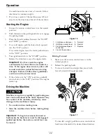
Page 26: ...lines can burn out the starter motor 6 If the choke is in the ON position gradually return choke to the OFF position as the engine warms up Driving the Machine CAUTION Machine can spin very rapidly by...

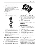
Page 27: ...e knobs on both sides of the control tower g314122 Figure 19 1 Motion control levers 2 Adjustment knob 3 Move the bar forward to obtain the fastest speed Move the bar backward to obtain the slowest sp...

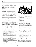
Page 28: ...control lever to the neutral position stop the engine and set the parking brake 2 Determine the amount of water needed to mix the amount of chemical needed as prescribed by the chemical manufacturer 3...

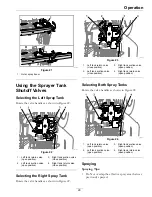
Page 29: ...Rotate the valve handles as shown in Figure 22 g311514 Figure 23 1 Left tank return valve close position 3 Right tank suction valve open position 2 Left tank suction valve close position 4 Right tank...

Page 30: ...r tank agitation To use the spray wand WARNING Spray wand traps liquids under high pressure even when engine is off High pressure spray discharge could cause serious injury or death Keep clear of nozz...

Page 31: ...he engine throttle to FAST 6 Set the three spray valves to ON 7 Allow the water in the tank to spray out through the nozzles 8 Check the nozzles to ensure that they are all spraying correctly 9 Remove...

Page 32: ...e steps to avoid damaging the spreader Note Clean your spreader thoroughly after all applications Before Operating the Spreader Make sure the spreader has been calibrated for the material to be spread...

Page 33: ...7 6 m g312556 Figure 28 1 Fence 3 Side deflector lowered 2 Flowers 5 Evaluate the spread pattern If adjustments are needed see the Spreader Calibration Pattern Adjustment section 6 When finished spre...

Page 34: ...Rate sections to calibrate the machine Determining the Distribution Pattern Operator supplied equipment 15 shallow collection pans and 15 graduated measuring cylinders The most accurate method to meas...

Page 35: ...from the spreader 11 To adjust the spreader pattern refer to the Spreader Pattern Adjustment section 12 Repeat steps 5 through 11 until an uniform pattern is achieved Determining the Effective Spread...

Page 36: ...e Amount Applied 25 lb 11 3 kg 20 lb 9 kg 5 lb 2 3 kg For this example 5 lb 2 3 kg was applied to 1 000 ft2 93 m2 9 If necessary adjust the rate dial to achieve the recommended amount to be applied an...

Page 37: ...control 4 Start notch if pattern is heavy to right side 2 Rotate counterclockwise to unlock 5 Rotate clockwise to lock 3 Start notch if pattern is heavy to left side 2 Lock the spreader pattern contro...

Page 38: ...results Approximate Dial Settings Type 1 000 ft2 93 m2 Dial Setting One Pass Dial Setting Two Passes 1 lb 45 kg 3 6 3 1 2 lb 91 kg 4 0 3 5 Fine Pellets 3 lb 1 36 kg 4 2 3 7 2 lb 91 kg 3 7 3 2 4 lb 1 8...

Page 39: ...1 2 m 1 lb 2 0 4 ft 1 2 m Blue Grass or Red Top 2 lb 2 5 4 ft 1 2 m 5 lb 2 5 4 ft 1 2 m 1 lb 3 0 4 ft 1 2 m Park Merion Delta or Kentucky Bluegrass 2 lb 3 5 4 ft 1 2 m 2 lb 2 75 2 25 6 ft 1 8 m 3 lb 3...

Page 40: ...as required by law Thoroughly read all of the safety instructions Knowing this information could help you your family pets or bystanders avoid injury To transport the machine Lock the brake and block...

Page 41: ...This will minimize the ramp angle The trailer or truck should be as level as possible Important Do Not attempt to turn the machine while on the ramp you may lose control and drive off the side Avoid s...

Page 42: ...storing Keep the machine guards shields and all safety devices in place and in safe working condition Frequently check for worn or deteriorating components and replace them with the manufacturer s re...

Page 43: ...ance Service Interval Maintenance Procedure After the first 5 hours Change the engine oil After the first 100 hours Change hydraulic system filter and fluid Check the wheel mount screw torque specific...

Page 44: ...tive clothing and use insulated tools DANGER Charging or jump starting the battery may produce explosive gases Battery gases can explode causing serious injury Keep sparks flames or cigarettes away fr...

Page 45: ...conditions exist 2 Make sure the booster is a good and fully charged lead acid battery at 12 6 volts or greater Use properly sized jumper cables 4 to 6 AWG with short lengths to reduce voltage drop b...

Page 46: ...t the other end of the positive cable to the positive terminal of the booster battery 5 Connect the black negative cable to the other terminal negative of the booster battery 6 MAKE THE FINAL CONNECTI...

Page 47: ...not operate Contact your authorized Z Turf Equipment Service Dealer Check the Normal Engine Starting Circuit System Operator Presence Control OPC Lanyard Outcome Engaged Starter should crank State of...

Page 48: ...drain plug is located on the left side of the engine Place pan under machine to catch oil Remove drail oil plug to open and allow oil to drain and reinstall valve when complete 4 Clean around oil fill...

Page 49: ...draulic system oil except for what can be drained when changing filter unless it is felt the oil has been contaminated or been extremely hot Changing oil unnecessarily could damage hydraulic system by...

Page 50: ...ck nozzle strainers and in line strainers 4 Replace as needed Check In line Filter Service Interval As required Periodically check the in line filter for any debris in the screen If debris is present...

Page 51: ...00 hours Remove spark plugs check condition and reset gaps or replace with new plugs See Engine Owner s Manual Wheel Mount Screw Torque Specification Service Interval After the first 100 hours Every 5...

Page 52: ...arging Wire Test A simple test can be used to test the DC output charging wire circuit If a wiring problem exists it can be corrected before testing regulator rectifier Leave stator wire harness disco...

Page 53: ...g or making any adjustments to the machine Pump Drive Belt Tension 1 Stop engine wait for all moving parts to stop and remove key Engage parking brake 2 Adjust tension by loosening or tightening the e...

Page 54: ...of the ball joints as shown in Figure 44 To increase the gap turn the control linkage counterclockwise To decrease the gap turn the control linkage clockwise g314362 Figure 44 1 Left motion control li...

Page 55: ...1 Stop engine wait for all moving parts to stop and remove key Engage parking brake 2 Clean all debris from rotating engine air intake screen around engine shrouding and exhaust system area 3 Wipe up...

Page 56: ...l and hydraulic oil are both pollutants to the environment Dispose of used oil at a certified recycling center or according to your state and local regulations Battery Disposal DANGER Battery electrol...

Page 57: ...of the sprayer tanks C Run the pump to distribute the anti freeze mix throughout the system D Set the spray levers position to begin spraying Allow the antifreeze to circulate through sprayer and nozz...

Page 58: ...nk is empty 1 Fill the fuel tank 2 The throttle and choke are not in the correct position 2 Be sure the throttle control is midway between the SLOW and FAST positions and the choke is in the ON positi...

Page 59: ...section in Operation 3 Nozzles are clogged 3 Unclog or replace nozzles 4 Hopper screen is plugged 4 Clean hopper screen 5 Material clumps over gate 5 Check motor shaft agitator pin presence Uneven spr...

Page 60: ...Schematics Schematics Electrical Schematic XL Models g314373 60...

Page 61: ...J1416 SW1402 PUMP Switch OFF ON P1404 1 3 4 6 8 P1404 2 5 7 K1402 86 87 30 87a PUMP RELAY 85 P1407 3 4 5 P1407 1 2 J1419 J1410 J1409 DIS1401 HOUR METER START REG DC GND S D REG ENG1401 ENGINE BRIGGS I...

Page 62: ...s schools and hospitals and on a wide variety of products Additionally some online and mail order retailers provide Prop 65 warnings on their websites or in catalogs How do the California warnings com...

Page 63: ...Service Record Date Description of Work Done Service Done By...

Page 64: ...te Purchased Engine Model No and Spec No Model No Engine Serial No E No Serial No www zturfequipment com Z Turf Equipment is part of the Exmark family of products 2020 Exmark Mfg Co Inc All Rights Res...

Reviews: