MASTERseries - Release 7.0
11
MASTERseries Quick Start Guide
2-Slot Chassis Installation
Power Lead Connection
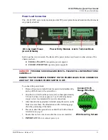
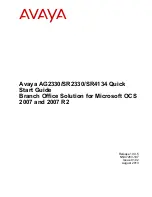
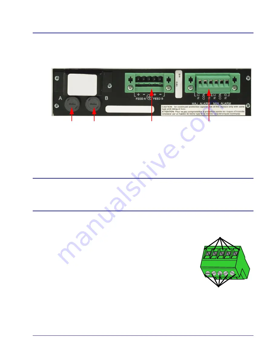
The +24/-48 VDC power entry module provides DC power protection and isolation when the leads
are properly attached.
Each input has its own return. The labels of the power entries vary based on what version of the
chassis you have:
z
FEED A (IN A/RTN A)
operates power supply A
z
FEED B (IN B/RTN B)
operates power supply B
DANGER!
POSSIBLE SHOCK HAZARD EXISTS - PLEASE FOLLOW INSTRUCTIONS
CAREFULLY.
ENSURE THAT NO POWER IS PRESENT ON THE POWER LEADS TO BE CONNECTED
AND THAT THE CHASSIS POWER SWITCH IS OFF.
To connect the power leads:
1. Remove the power terminal block for easier lead attachment by
prying off the block with a screwdriver.
2. Strip the two wires from the power source so that approximately
5/16 inch of bare wire is exposed. 16 or 18 AWG insulated
copper wire is recommended for power connections.
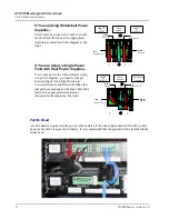
3. Attach leads to the appropriate terminals using the screws on the
block to secure them. The illustrations on the following page
show the positioning of the leads.
4. Be sure to attach the ground wire as described in
Rack Mount
Installation on page 8
.
5. Ensure that no bare wire shows after the wires are installed.
6.
IMPORTANT:
Do not connect power yet.
Power Entry Module Alarm Terminal Block
DC Line Input Fuses
(A and B feeds)
Connect 16-18
Wire Securing Screws
Gauge Wire Here


