24
MASTERseries - Release 7.0
MASTERseries Quick Start Guide
8-Slot Chassis Installation
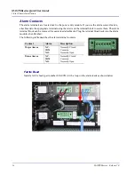
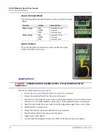
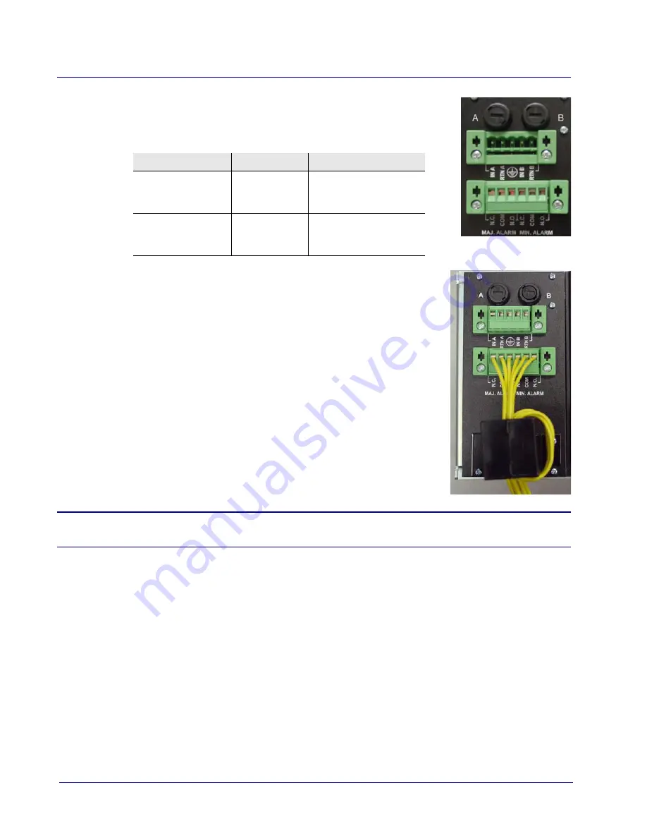
Alarm Terminal Block
The following table describes the alarm contacts on the DC powered
chassis.
Alarm Contact
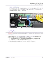
If you use the alarm contact feature, install a ferrite bead (part
number 010-0051) with a loop.
Applying Power
DANGER!
POSSIBLE SHOCK HAZARD EXISTS - FOLLOW INSTRUCTIONS
CAREFULLY.
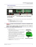
Wire Feed A and Feed B to a power source:
1. Ensure that no power is present on the two wires to be connected.
2. Remove the terminal block from the power entry panel.
3. Strip the two wires from the power source so that approximately 5/16 inch of bare wire is
exposed. 16 or 18 AWG insulated copper wire is recommended for power connections.
4. Insert the wires (from the power source) into the appropriate square holes, one at a time.
5. Tighten screws to clamp wires.
6. Ensure that no bare wire shows after the wires are installed.
7. Plug the terminal block into the power entry panel.
8. Apply power to the chassis.
9. A green light should appear on the power LED on the front of the power supply.
Contact
Alarm
Description
Major Alarm
N.C.
COM
N.O.
Normally Closed
Common
Normally Open
Minor Alarm
N.C.
COM
N.O.
Normally Closed
Common
Normally Open

