14
【
rectangular
】
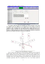
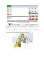
coordinate system to obtain point P6, namely The X direction of the tool
coordinate is the same as the X direction of the rectangular coordinate).
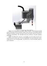
3) SCARA tool coordinate calibration
Step 1: make two tip calibration rods (the sharper the better), one is installed at the
center of the tool to be calibrated (you can use the tip of the tool itself), and the other is
placed horizontally on the workbench (you can use it in the second step Placed).
Step 2: Switch to the
【
joint
】
coordinate system and the teach pendant robot moves
out of zero; switch to the
【
rectangular
】
coordinate system and teach the robot, adjust RZ to
0 radians, and align the two tips (movable work The tip calibration rod on the stage is
aligned, and it cannot be moved after being placed). The X, Y coordinate values at this
time are recorded as X1, Y1.
Step 3: In the
【
rectangular
】
coordinate system mode, teach the robot, adjust Rz to
3.141 radians, continue to teach the robot, and align the two tips. The X, Y coordinate
values at this time are recorded as X2, Y2.
Step 4: Calculation
2
1
2
x
x
x
2
1
2
y
y
y
x,y is the tool coordinate parameter, select a tool coordinate on the teach pendant, fill
in the x,y value, the rest is 0.
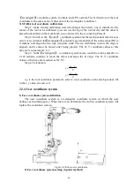
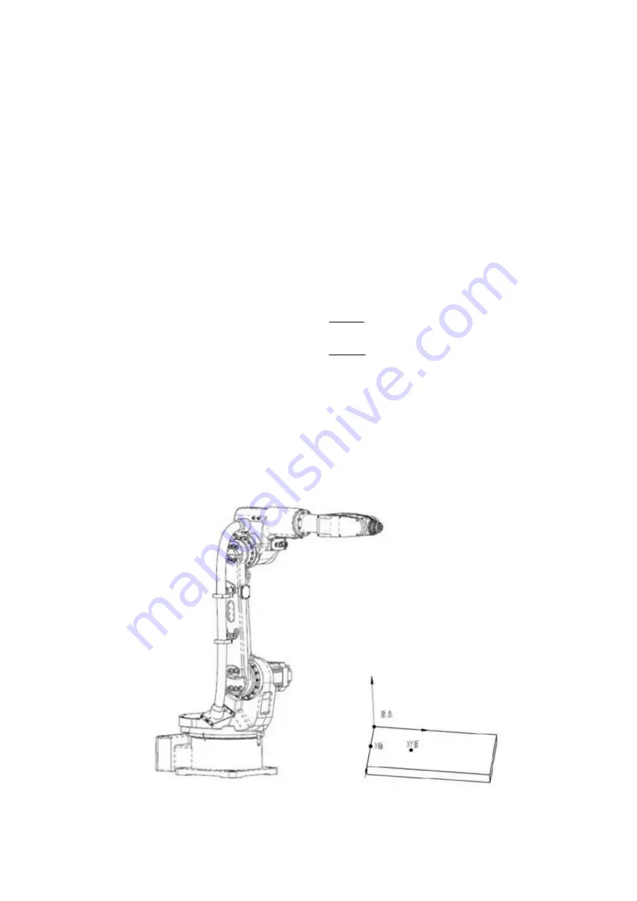
2.2.4 User coordinate system
1) User coordinate system definition
The user coordinate system is a rectangular coordinate system in which the user
defines each working space. When there is no definition, the world coordinate system will
replace the coordinate system.
Figure 2-8 Robot user coordinates
2) User coordinate system setting (3-point method)


