background image

77

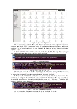
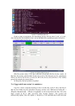
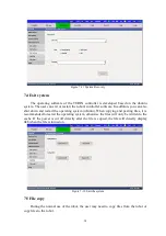
the new system. The system upgrade is now complete.

Figure 7-9 New system upgrade

7.2 System backup

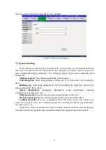
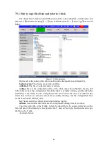
If the software system needs to be backed up, or when there are operational problems

that need to be resolved by the manufacturer, the customer is generally required to provide

some operational-related parameters. The following figure shows some commonly used

parameters.

Software system:

The software system the robot is using.

Collecting data:

Some data generated during the use of the robot, not commonly

used.

Running log:

Some logs generated by the robot during its operation, such as the

status information of the robot.

Alarm information:

debugging information, point information, network

communication information, etc.

Motion program:

Save the foreground running program of the robot.

Background program:

Save the background motion program of the robot.

Configuration file:

Save the configuration file of the robot, such as the robot's zero

point, dh, activation code, vision tracking parameters, welding parameters, tool parameters,

user parameters, etc.

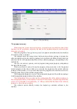
Select the U disk and stand-alone need to backup content, and then start the backup.

The backup will only pack the files and will not delete the original files in the system.

Summary of Contents for TKB80306

Page 1: ...Shanghai Turing Intelligent Manufacturing Robot Co LTD ...

Page 2: ...restore the cover or safety cover as specified and then run according to the instructions The drawings and photos in the manual are representative examples and may be different from the purchased products The manual is sometimes modified due to product improvement specification change an the fact that the manual itself is easier to use and other appropriate reasons The company is not responsible f...

Page 3: ...obot axis 9 2 1 1 Definition of robot axis 9 2 1 2 Robot joint motion 9 2 2 Robot coordinate system 10 2 2 1 Joint coordinate system 11 2 2 2 Cartesian coordinate system 11 2 2 3 Tool coordinate system 12 2 2 4 User coordinate system 14 2 3 Robot zero point and calibration 15 2 3 1 Robot zero 15 2 3 2 Battery replacement 17 2 3 3 Twenty point correction method 18 Chapter 3 Basic programming 22 3 1...

Page 4: ...ement 43 3 5 1 Open the program 43 3 5 2 New program 43 3 5 3 Rename program 44 3 5 4 Remove program 44 3 5 5 Finder and file sorting 45 Chapter 4 Advanced robot debugging 47 4 1 Input Output 47 4 1 1 I O control 47 4 1 2 DA Control 47 4 1 3 Encoder 48 4 2 Variable 48 4 2 1 Variable usage instructions 48 4 2 2 Variable use 49 4 2 3 Variable automatic storage 52 4 3 Run settings 52 4 3 1 Reference ...

Page 5: ...er 6 System parameters 68 6 1 Basic Settings 68 6 1 1 Zero calibration 68 6 1 2 Connecting rod parameters 68 6 1 3 Joint parameters 69 6 1 4 Spatial parameters 70 6 1 5 Twenty points calibration 70 6 1 6 Robot model 71 6 2 System settings 71 6 2 1 Key definition 71 6 2 2 Log print settings 72 Chapter 7 System maintenance 74 7 1 System Upgrade 74 7 1 1 Upgrade from version 1 5 and below to version ...

Page 6: ...IV IV 8 2 Common faults and treatment 82 ...

Page 7: ...bot 1 Security risks during installation and service of robots 1 For the safety precautions of the robot please refer to the installation and maintenance chapter 2 The emergency stop button of the system must be in a position that is easy to touch to ensure that the robot can be stopped in an emergency when an accident occurs 3 The operator must make sure that the installed safety facilities are a...

Page 8: ...e during transportation storage and use especially the connectors Motor reducer Security risk Specific description The reducer is easily damaged by improper external force Regardless of when the motor reducer is disassembled or when the motor reducer is installed the reducer is easily damaged under excessive improper external force 4 Pay attention to the parts in the robot that are easy to get hot...

Page 9: ... of control the operator can turn off the robot outside the working range of the robot Operator s electrical hazard Operators need to pay attention to high voltage hazards 1 The power line of the servo motor 2 Connect fixtures and other external equipment After the robot is turned off the external equipment of the robot may still be running so the power cord of the external equipment may also caus...

Page 10: ...below 250mm s When the robot needs to be adjusted to full manual speed it can only be operated by professionals who fully understand the risks 3 Pay attention to the rotation joints of the robot to prevent the hair and clothes from being caught in the joints at the same time pay attention to other dangers that may be caused by the movement of the robot or other auxiliary equipment 4 Test whether t...

Page 11: ...et as shown in the figure below Of course users can also set their own emergency stop button as needed 1 3 Safety precautions for robot operation Before use installation operation maintenance overhaul please be sure to thoroughly read and fully grasp this manual and other auxiliary materials and start to use after you are familiar with all equipment knowledge safety knowledge and precautions The s...

Page 12: ...ial attention to the working conditions of the repaired parts during the test Note When letting the robot go through the program pay special attention to potential interference hazards 1 3 4 Electrical hazard Overview The electric control cabinet is the center of the control robot Any misoperation of the electric control cabinet may cause electric shock and robot misoperation which in turn may cau...

Page 13: ...s necessary to operate the oil or reducer at a high temperature of 90 degrees and the operator may be allergic to the oil Therefore wear protective measures gloves to carry out this work Beware of sputtering When opening the oil chamber there may be pressure in the oil chamber to cause sputtering So be careful when opening the oil chamber cover and stay away from the opening do not fill too much w...

Page 14: ... fixture and it must be empty In the event of an accident or abnormal operation of the robot you can use the emergency stop button to stop the operation Because the robot is in the automatic state even if the running speed is very low its momentum is still very large so when programming testing and maintenance work the robot must be placed in manual mode The pressure in the gas circuit system can ...

Page 15: ...vided into sliding table and positioner Unless otherwise specified the robot axis refers to the motion axis of the robot body 2 1 2 Robot joint motion Turing robots are divided into three types of industrial robots Industrial six axis robot including six rotation axes SCARA contains three rotation axes and one translation axis Palletizing manipulator including four rotating shafts The joint motion...

Page 16: ...e world coordinates see 2 2 1 The direction of the four fingers is the positive direction of rotation and the reverse direction is the negative direction of rotation 2 2 Robot coordinate system In teach mode the robot axis movement is related to the currently selected coordinate system Turing robot supports 4 kinds of coordinate systems joint coordinate system rectangular coordinate system tool co...

Page 17: ...he direction corresponding to the schematic diagram In the coordinate system select the positioner coordinate system then press the J1 J3 axis operation button the action will be the external three axes 2 2 2 Cartesian coordinate system Figure 2 4 Cartesian coordinate system The origin of the Cartesian coordinate system is defined on the axis of the robot 1 axis and it intersects with the base mou...

Page 18: ...rection of tool 00 is consistent with the direction of the world coordinate system Tool 01 10 generally defines the effective direction of the tool as the Z axis direction of the tool coordinate system A simple tool can directly input the size of the tool and the angle of rotation Complex tools such as welding torches are generally calibrated by the six point method The specific calibration method...

Page 19: ...is dead and the mechanical transmission parts have been replaced the robot needs to be re calibrated Figure 2 7 Six point calibration of robot pose Note As shown in the figure above P1 P4 and the tip calibration rod are scattered at a certain angle and the posture change of the point should be as large as possible the effective direction of the P5 point tool should be in line with the tip calibrat...

Page 20: ...k The tip calibration rod on the stage is aligned and it cannot be moved after being placed The X Y coordinate values at this time are recorded as X1 Y1 Step 3 In the rectangular coordinate system mode teach the robot adjust Rz to 3 141 radians continue to teach the robot and align the two tips The X Y coordinate values at this time are recorded as X2 Y2 Step 4 Calculation 2 1 2 x x x 2 1 2 y y y ...

Page 21: ...ts all use Ehercat bus type servos which rely on multi turn absolute encoders of servo motors to record positions The multi turn absolute encoder is equipped with a 3 6V battery recording position and there is no need to change it when starting up However when the battery is empty and the battery is replaced the robot collides or the transmission component is replaced and the zero position is lost...

Page 22: ...inary judgment to determine the zero position and then use the software to correct the deviation see 2 3 3 There are the following methods to judge the zero position initially Visually or with the aid of a spirit level to observe the robot arm horizontal or vertical Align the zero mark of each joint of the robot The zero marks of different robots will be slightly different The following are two ba...

Page 23: ...he encoder battery on the back of the robot base and measure the battery voltage with a multimeter The normal rated voltage is 3 6V When the voltage is lower than 3 2V the battery needs to be replaced The encoder batteries of Turing robots are all installed on the back cover of the base and the battery can be replaced by removing the back cover some models have a small battery cover only need to r...

Page 24: ...o position needs to be within the allowable deviation The specific calibration steps are as follows Step 1 make two tip calibration rods the sharper the better one is installed at the center of the tool to be calibrated you can use the tip of the tool itself such as welding wire but you need to sharpen it and the other is placed horizontally at work on stage not movable Step 2 Create a new file on...

Page 25: ...see Figure 2 16 and the greater the difference in the posture of the robot the better When making a four axis robot at 20 o clock place the tip calibration rod on the worktable at any position within the robot s motion range and record two joint motion commands with left and right hand postures see Figure 2 17 Ten positions are scattered in the robot s movement range and the more dispersed the bet...

Page 26: ...he calculation a window will pop up to show the progress After the calculation is completed click OK The information bar below will show 20 points calculated successfully Step 5 Click Save to bring up a window Do you want to update directly to the connecting rod zero point tool if you click OK the system parameters will be changed directly if you click Cancel or not Save you need to manually updat...

Page 27: ...0 point calibration NormErr Tool coordinate error DeltaDH Calculated connecting rod parameter error DeltaZero Calculated zero error Note Generally speaking the value of calibration will not exceed 5mm If it exceeds 5mm it may be the problem of joint parameter setting It is recommended to calibrate after checking the correctness ...

Page 28: ...gramming interface 3 1 1 Teach pendant structure Figure 3 1 Teach pendant structure Emergency stop switch Normally closed is effective and disconnected when photographed the robot switches to emergency stop mode Key switch Switch between manual teaching mode teach automatic reproduction mode play mode Enabling switch only useful in the teaching mode the switch is divided into three gears open pres...

Page 29: ...axis three axis forward and reverse rotation J4 J4 Four axis forward and reverse rotation forward and reverse rotation around the X axis Rx J5 J5 Five axis forward and reverse rotation forward and reverse rotation around Y Ry J6 J6 Six axis forward and reverse rotation forward and reverse rotation around Z Rz SA In playback mode start running BK The robot returns to zero ST In playback mode stop r...

Page 30: ...nual automatic mode switching program running and program stop operation can be performed When the equipment is debugged only need to start and stop production every day no need to log in 2 Operator login The operator has the authority to modify programming and point teaching During commissioning or when replacing the product and re teaching the point operator login is required Operator login sett...

Page 31: ... system selection in the toolbar on the upper right corner of the touch screen there are joint right angle tool user and positioner external axis coordinate system can be selected you can switch the robot coordinate system To the corresponding coordinate system 3 2 3 Tool and user coordinate system number selection In the toolbar you can select the tool and user coordinate system number ...

Page 32: ...anual teaching 3 2 5 Manually operated robot Hold the Teach Pendant with your left hand and press and hold the Enable Switch the right hand can operate the corresponding axis movement See Table 3 1 for key functions 3 3 Programming In this section a complete basic program will be introduced but to complete more complicated programs or use more advanced commands you need to consult other chapters 3...

Page 33: ...27 Figure 3 8 Add instruction Enter the value in the pop up window and click New Figure 3 9 New command After completion see the figure below ...

Page 34: ...by default When the cursor selects the first line to add an instruction a dialog window will pop up Please select the first line or the second line Figure 3 11 Position of the first command line 3 3 2 Deletion of instructions Select the command to be deleted click Delete Command enter the number of lines to be deleted and click OK ...

Page 35: ...as no specific format and framework Any complete instruction can constitute a program the program is only related to the requirements what tasks need to be completed then edit what program Note The program does not have a specific format that can be framed but the instructions must be written according to the specifications otherwise the compilation will fail For instructions on the instructions p...

Page 36: ... on the current teach pendant In the following chapters instructions will be divided into five categories and introduced separately In addition to the instructions on the teach pendant there are background instructions please refer to the Debugging Manual Figure 3 15 Command collection 3 4 1 Motion instruction Usually the motion command records the position data motion type and motion speed ...

Page 37: ... corresponding to the joint motion type is joint motion English command MOVJ In general for safety the joint motion type is used at the beginning of the program The characteristics of the joint motion type are the fastest speed and the unknown path Therefore this type of motion is generally used at a spatial point and before running the program automatically it must be checked at a low speed to ob...

Page 38: ...inear motion during motion the robot motion control point goes straight and the posture of the fixture changes automatically The operation of adding the linear motion instruction is as follows The end point of the previous motion command is the start point of linear motion Manually move the robot to the end point of linear motion Click Add Command Motion Command Linear Motion enter the speed accel...

Page 39: ...es We need to have two instructions The operation of adding the Circular Motion instruction is as follows The end point of the previous motion command is the starting point of circular motion Manually move the robot to the auxiliary point of circular motion Click Add command Motion command Circular motion enter the speed acceleration smoothing and After related parameters such as tools and user co...

Page 40: ...osition When the robot is recording the position the current position of the robot is recorded in the motion command If you need to modify the position in the instruction manually move the robot to the position you want to record and repeat the operation process of recording the movement instruction When recording the instruction into the job press Change Point OK Figure 3 23 Change the position o...

Page 41: ...on Coordinate system instructions can automatically modify coordinate system information in the program The overall offset coordinate system can offset all motion commands based on this coordinate system in the program The offset can be either constant or variable Figure 3 25 Coordinate command Add offset to tool coordinate system ...

Page 42: ...r the coordinate point variable and the coordinate point register is read and modified It is often used when guiding robots with machine vision Based on the communication method change the coordinate information of the target point Coordinate point storage is based on joints and rectangular coordinate systems Pay attention to the consistency of the coordinate system when modifying and calling ...

Page 43: ...trol IO output Control the target IO output port status If the negation function is set it can be negated automatically after a certain time delay Figure 3 29 Control IO output 2 Wait for IO input The program is blocked here When the IO status meets the set conditions the program continues to run ...

Page 44: ...ng exercise The instruction is added before the motion instruction Corresponding actions can be executed during the movement of the motion instruction for example IO output variable change etc Figure 3 32 Trigger action during movement 5 Trigger stop during exercise When the motion command is running the conditions set in the trigger stop command are satisfied and the robot can stop the motion in ...

Page 45: ...r details please refer to Chapter 5 and Debugging Manual 3 4 5 General instructions and logic instructions 1 Regular Instructions The general instructions include instructions for operating the controller variables adding delays and adding comments Figure 3 34 General instructions Variable operation Modification and calculation of digital variables character variables IO output status etc ...

Page 46: ...continue to execute the next instruction Figure 3 36 New Delay Notes Add comments to the program to increase the readability of the program Figure 3 37 New Note 2 Logic instructions Logic instructions can perform logic operations and are indispensable instructions for performing complex functions ...

Page 47: ...tiple states Otherwise if not otherwise the compilation cannot pass When judging again under a condition you need to add a conditional statement again using a nested structure Figure 3 39 Conditional instructions Loop statement The condition after the loop statement meets the set condition and the program repeatedly executes the content in the loop body ...

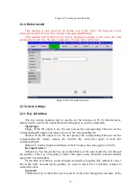
Page 48: ...e Figure 3 41 Waiting statement Jump statement Unconditional jump Once the program executes the jump to instruction the next step is to find the corresponding mark and continue running Figure 3 42 Jump statement Program related operations instructions related to program control Figure 3 43 Program instructions ...

Page 49: ... can perform it under the File Operation menu Including Open New Copy Rename Delete Find Sort these operations 3 5 1 Open the program The method of selecting the foreground job teaching job and the background job program are the same but the menu position is different The menu position and operation of the selection operation of the foreground operation Select the file you want to open and click t...

Page 50: ...le 3 5 3 Rename program Select the file and click Rename After modifying the name click Rename As shown below Figure 3 46 Rename file 3 5 4 Remove program Select the program to be deleted and click Delete OK As shown below ...

Page 51: ...tion In the teaching mode click the Search button enter part of the letter of the file to be found click Search and enter the content to be found Figure 3 48 Search program 2 File sorting You can sort the files according to the file size time and alphabetical order ascending order descending order Just click the same button in the lower right corner This button will switch between these modes See ...

Page 52: ...46 Figure 3 49 Sorting files ...

Page 53: ...es with peripheral equipment through IO signals After hard wiring the user needs to check the current IO status You can use Monitor Control Input Output I O Control to view the current IO status Figure 4 1 IO control 4 1 2 DA Control Welding process analog communication with welding machine generally use DA control ...

Page 54: ...e encoder check the current position and running status of the encoder through Monitor Control Encode Figure 4 3 Econder 4 2 Variable 4 2 1 Variable usage instructions 1 Variable type There are three types of variables that can be used in the control system which are numeric variables floating point numbers character variables 1024 bytes and ...

Page 55: ... the main file and each sub file 3 Definition of variables There are two ways to define variables one is system pre defined and the other is user defined Some system variables and file variables have been defined in the system for users to use Global variables are not predefined in the system and can be replaced with system variables if necessary The user defined variable method is more suitable f...

Page 56: ...50 Figure 4 4 System V variables Figure 4 5 System S variables ...

Page 57: ...corresponding file The parts that can be changed in the interface are variable value and variable comment Coordinate point variables support manual input and direct recording of the current position There are two ways to change the value Use the SA key to move to this point The variable values of all interfaces will be refreshed in real time so this interface can be used to monitor variable values...

Page 58: ...ored in the file In order to use the changed value the next time the script is started Note Because the current hardware system does not have power off protection measures when the program is running abnormal power off behavior such as screwing the power supply may cause the value that has just been changed to fail to be stored in the file This point requires special attention 4 3 Run settings 4 3...

Page 59: ...n detecting whether the robot is at the reference point 10 Reference point the exact value of the reference point of the robot 11 Reference point right value the floating positive right value when detecting whether the robot is at the reference point Description 1 On this page you can use the SA key joint to run to the reference point the prerequisite is that the reference point must be turned on ...

Page 60: ...e zone Set a center point and offset relative to the center point in front back left and right three directions of world coordinates XYZ to form a cubic interference zone 4 4 Ethernet communication 4 4 1 Robot IP configuration Turing robots can communicate with peripheral devices through the network For example modbus tcp remote command control remote browser control visual communication custom pr...

Page 61: ...ameter Setting System Maintenance Exit System Exit Controller System the interface is as follows Figure 4 12 Exit the control system Exit the TURIN controller system enter the Ubuntu desktop the network icon in the upper right corner of the stand alone interface the interface is as follows ...

Page 62: ... First enable the network and choose to edit the connection Figure 4 14 Enabling the network and connecting to the network Edit IP Figure 4 15 Edit IP Select manual IP configure the IP as shown below save it and then restart the system ...

Page 63: ...rnet status as shown below Figure 4 17 View Ethernet status The parameters related to the Ethernet address are consistent with the set values that is the settings are correct 4 4 3 Communication test After the IP settings of both parties are completed IP testing can be performed Parameter setting System setting Ping the interface is as follows ...

Page 64: ...n If the user needs not to use the teaching pendant the robot interface can be accessed through the host computer browser At this time the functions of enabling emergency stop switching teaching reproduction etc need to be operated by buttons on the cabinet For detailed instructions please refer to the Debugging Manual document 4 5 2 Remote command If the user needs to control the robot through th...

Page 65: ... number configured by the robot default 8527 note that the port cannot be set to 502 this port setting is set to modbus by default tcp communication port Then the standard XML format function will be used to open the interface as shown below Figure 4 20 XML format function is enabled ...

Page 66: ...e welding machine it is necessary to make corresponding settings according to the basic characteristics of the welding machine and the connection circuit between the welding machine and the control cabinet In the main menu select Process and then select Welding Process you can set the welding process parameters including basic settings arc starting welding arc extinction swing arc settings voltage...

Page 67: ...e welding machine so that they can operate according to the welding machine during welding The voltage and current are reversely calculated to calculate the voltage value that the controller needs to output Click to make the controller output the corresponding voltage value At this time fill in the voltage or current value displayed on the welding machine After all 20 files have been input click S...

Page 68: ... time and then press Exit Save Ø Swing setting used to set the swing mode such as Z shaped pendulum arc pendulum and sinusoidal pendulum Ø Swing frequency Set the number of swings per second Ø Swing amplitude Set the distance of one side swing Ø Left stay time set the stay time when swinging to the left vertex Ø Right stay time set the stay time when swinging to the right vertex Note After setting...

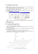
Page 69: ...sh select this command to extinguish the arc of the welding machine 5 2 Palletizing process 5 2 1 Typical palletizing applications Pallet User defined robot table usually flat Row in a plane parallel to the tray the working points are arranged in a straight line perpendicular to the column Column In a plane parallel to the tray the working points are arranged in a straight line perpendicular to th...

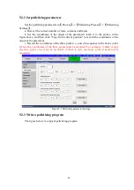
Page 70: ... click Copy from current position to record the coordinates of the origin of the placement c Record the coordinates of the three point b c and d in sequence in the above order If not the coordinates of the three points must be recorded For example if there is only one line point c need not be recorded if there is only one layer point d need not be recorded Figure 5 7 Palletizing parameter settings...

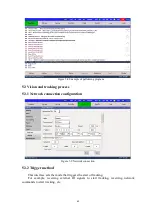
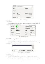
Page 71: ...process 5 3 1 Network connection configuration Figure 5 9 Network connection 5 3 2 Trigger method This interface sets the mode that triggers the start of tracking For example receiving external IO signals to start tracking receiving network commands to start tracking etc ...

Page 72: ... tracking calibration When the tracking track is an arc track the user needs to calibrate the arc track The simple translation tracking method does not need to set the disk tracking calibration Figure 5 12 Disk tracking calibration 5 3 5 Calibration After the visual calibration the coordinates can be transformed in the controller Vision only needs to send pixel coordinates and the robot can conver...

Page 73: ...7 coordinates to perform actions Just install the calibration board at the end of the robot and run the calibration script automatically Eliminate the need for manual calibration Figure 5 13 Calibration ...

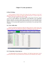
Page 74: ...d for the operator to change at will Improper modification will cause the robot to work abnormally Therefore it is recommended that manufacturers use this interface to set parameters before debugging 6 1 1 Zero calibration On the zero calibration interface the following figure shows the current encoder value and current joint angle The right most column is to calibrate the zero point calibration o...

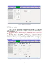
Page 75: ...meter affects the running speed of the robot and the customer cannot modify it by himself The system automatically calculates it and only needs to modify the speed to calculate the maximum speed of the shaft if you modify the acceleration multiple the maximum acceleration and the maximum stop speed will be displayed in real time Note that this is for display only and will not be saved in real time...

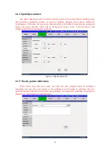
Page 76: ...alarm will occur and the robot will be damaged in severe cases or the trajectory will change and hit the surrounding equipment Figure 6 4 Spatial parameters 6 1 5 Twenty points calibration If the robot loses the zero point not only the zero position must be calibrated manually but also the robot needs to be calibrated at 20 points to calibrate the zero position and the link error Customers are gen...

Page 77: ...e corresponding button to set the corresponding IO output and release it to reset the corresponding IO Double If the IO output is set the user presses the corresponding button to set the corresponding IO output release the shortcut key and press again to reset the corresponding IO Button F1 Set the function definition of the F1 button the same applies to F2 F4 Key input source Subsystem You can ge...

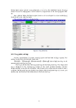
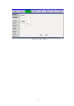
Page 78: ...f system running speed and hard disk storage capacity the setting of print log is divided into four levels Error Warning Information Debug Select high level log it will automatically print low level log The Log is divided into the foreground log and the background log The foreground log is displayed in the running log column of the teach pendant interface and the background log is saved in the log...

Page 79: ...73 Figure 6 8 Log print settings ...

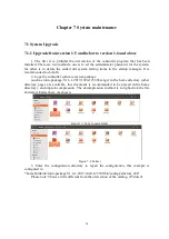
Page 80: ...ller software system package such as turin package V1 6 1 2017 1024 123306 tar gz to the home directory other directory pages are available this document is recommended to be placed in the home directory and unpack compression The decompression method is to right click the file and select Extract here As shown Figure 7 1 Copy to main folder Figure 7 2 Extract 3 Enter the configuration directory to...

Page 81: ...1 2017 1024 123306 bin Figure 7 4 Open the terminal Figure 7 5 Enter the bin directory The new version of the controller has many more functions among which turin tools is responsible for system installation maintenance and other functions 5 Execute the installation command the new version only needs to execute one command to complete the installation sudo turin tools install by the way uninstall ...

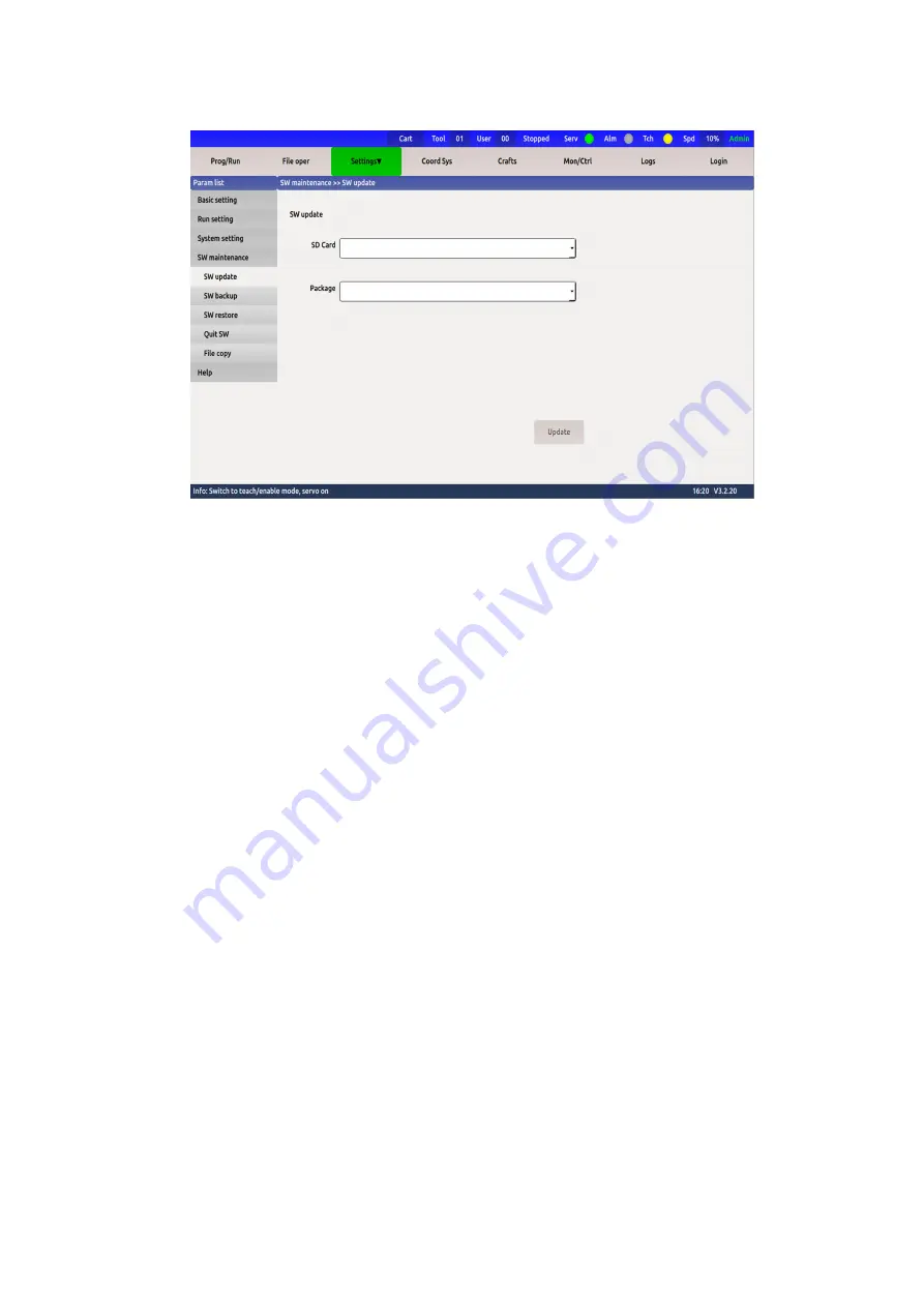
Page 82: ... department When you receive the license you need to fill in the license and click Save The validity period will indicate the license status At this point the new system is installed 7 1 2 Upgrade from version 1 6 and above Copy the version compressed package to the root directory of the U disk insert the U disk into the USB port of the industrial computer and then enter Parameter Settings System ...

Page 83: ...sed Running log Some logs generated by the robot during its operation such as the status information of the robot Alarm information debugging information point information network communication information etc Motion program Save the foreground running program of the robot Background program Save the background motion program of the robot Configuration file Save the configuration file of the robot...

Page 84: ...ground program configuration file and software system When you choose to restore the motion program what you restore is the foreground motion program of the robot which is to overwrite the program in the picture software package to the machine or to overwrite directly If the program in the machine needs to be retained please back up the machine program first The background program is to cover the ...

Page 85: ...tart the operating system ubuntu When copying and pasting files it is recommended to restart the operating system otherwise the files will only be written to the cache If the power is cut off directly after the file is copied the file will directly display 0kb when the file is turned on Figure 7 12 Exit the system 7 5 File copy During the normal use of the robot the user may need to copy files fro...

Page 86: ...ubfolder ethercat_x86 is the folder where the configuration file of the robot is actually running and the subfolder simulation is the folder for the configuration file saved when the robot is simulated the client does not have a version to run All are actually running and the configuration files are all saved under ethercat_x86 log Saved under this folder is the robot running log file motion Saved...

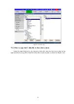
Page 87: ... How to copy the U disk file to the robot system Select the target directory to be copied to on the left select the file to be copied on the right and click to copy the U disk file to the robot control system as shown in Figure 7 14 ...

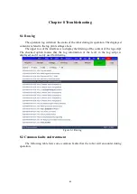
Page 88: ...gs above The upper row of the interface is to display the filtering of the content of the log script The checked option means that the log information of the level in the log script is displayed and it is only used for filtering Figure 8 1 Run log 8 2 Common faults and treatment The following table lists some common faults that the robot will encounter during operation ...

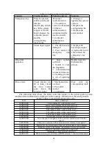
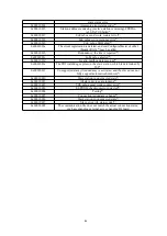
Page 89: ...eck the external wiring 1 Mechanical jam overload 2 Poor cable contact 3 Lost battery Deal with the corresponding fault The following table shows the alarm codes that appear in the robot control system and the alarm information is displayed in the message column below the teach pendant Table 8 2 Alarm codes at the front desk of the robot 0x65 Slave is missing 0x00010001 Cycle command work counter ...

Page 90: ...d mailbox data received 0x0001001e The PDI watchdog expires on the slave station which is determined by IST 0x0001001f Unsupported slave if redundancy is activated and the slave does not fully support automatic shutdown 0x00010020 Slave station in unexpected state 0x00010021 All slave devices are running 0x00010022 VOE mbox send work counter error 0x00010023 EEPROM checksum error detected 0x000100...

Reviews: