background image

52” Belmont Ceiling Fan

Owner’s Manual

Ventilador de Techo de 132.1cm

Manual del Propietario

SKU 355-7004

LISTED

Summary of Contents for BELMONT 52

Page 1: ...52 Belmont Ceiling Fan Owner s Manual Ventilador de Techo de 132 1cm Manual del Propietario SKU 355 7004 LISTED ...

Page 2: ... or questions regarding installation Please reference your SKU 355 7004 oil rubbed bronze or UPC 082392 636050 oil rubbed bronze Safety Rules 1 Unpacking Your Fan 2 Installing Your Fan 3 Operating Your Fan 10 Care of Your Fan 11 Troubleshooting 11 Specifications 12 Warranty Information 13 Table of Contents UL Model No EF200M A 52 ...

Page 3: ...e suitable for most cleaning 11 After making electrical connections spliced conductors should be turned upward and pushed carefully up into outlet box The wires should be spread apart with the grounded conductor and the equipment grounding conductor on one side of the outlet box 12 Electrical diagrams are for reference only Light kits that are not packed with the fan must be UL listed and marked s...

Page 4: ...ed inside canopy 7 Decorative Motor Collar Cover 1 Fan Motor Assembly 2 Canopy 3 Blades 5 4 Blade Bracket Set 5 5 Ball Downrod Assembly 2 Unpacking Your Fan IMPORTANT THIS PRODUCT AND OR COMPONENTS ARE COVERED BY ONE OR MORE OF THE FOLLOWING U S PATENTS 5 947 436 5 988 580 5 971 573 6 010 306 6 039 541 6 046 416 AND OTHER PATENTS PENDING Unpack your fan and check the contents You should have the f...

Page 5: ...You may need a longer downrod to maintain proper blade clearance when installing on a steep sloped ceil ing The maximum angle allowable is 30 If the canopy touches down rod remove the decorative canopy bottom cover and turn the canopy 180 before attaching the canopy to the mounting plate Outlet Box To hang your fan where there is an existing fixture but no ceiling joist you may need an installatio...

Page 6: ...standard ceiling installation using the downrod with ball and socket mounting and the close to ceiling mounting The close to ceiling mounting is recommended in rooms with less than 8 foot ceilings or in areas where additional space is desired from the floor to the fan blades When using standard downrod installation the distance from the ceiling to the bottom of the fan blades will be approximately...

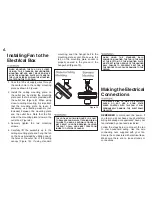
Page 7: ...r screws on the top of the canopy Remove the two non slotted screws and loosen the slotted screws This will enable you to remove the mounting plate Figure 5 2 Remove the decorative canopy bottom cover from the canopy by depressing the three studs Figure 7 3 Remove three of the six screws and lock washers every other one securing the reinforcing plate to the top of the fan mo tor housing Figure 8 M...

Page 8: ...N USING THE STANDARD BALL DOWNROD MOUNTING THE TAB IN THE RING AT THE BOTTOM OF THE MOUNTING PLATE MUST REST IN THE GROOVE OF THE HANGER BALL FAILURE TO PROPERLY SEAT TAB IN THE GROOVE COULD CAUSE DAMAGE TO THE WIRING TO REDUCE RISK OF FIRE OR ELECTRIC SHOCK DO NOT USE A SOLID STATE SPEED CONTROL WITH THIS FAN IT WILL PERMANENTLY DAMAGE THE ELECTRONIC CIRCUITRY 6 Making the Electrical Connections ...

Page 9: ... mounting plate since the ball downrod assembly is not used 2 Connect the fan motor white wire to the supply white neutral wire using a wire nut Figure 11 3 Connect the fan motor black wire to the supply black hot wire using a wire nut Figure 11 4 Turn wire connections upward spread ing them apart so the green ground and white wires will be on one side of the outlet box and the black and blue wire...

Page 10: ...nopy and tighten firmly 3 You may now proceed to attaching the fan blades CLOSE TO CEILING MOUNTING 1 Carefully unhook the fan from the mounting plate and align the locking slots of the ceiling canopy with the two screws in the mounting plate Push up to engage the slots and turn clockwise to lock in place Immediately tighten the two mounting screws firmly LOCKING SLOTS OF CEILING CANOPY ARE PROVID...

Page 11: ...re caused when blade levels are unequal Check this level by selecting a point on the ceil ing above the tip of one of the blades Measure from a point on the center of each blade to the point on the ceil ing Measure this distance as shown in Figure 14 Rotate the fan until the next blade is positioned for measurement Repeat for each blade Measurement deviations should be within 1 8 Run the fan for 1...

Page 12: ... TO STOP BEFORE REVERSING THE DIRECTION OF THE BLADE ROTATION Warm weather Forward A down ward air flow creates a cooling effect as shown in Figure 15 This allows you to set your air conditioner on a higher setting without affecting your comfort Cool weather Reverse An upward air flow moves warm air off the ceiling are as shown in Figure 16 This allows you to set your heating unit on a lower setti...

Page 13: ...R IS OFF AT THE ELECTRICAL PANEL BOX BE FORE YOU ATTEMPT TO MAKE ANY REPAIRS REFER TO THE SECTION MAKING ELECTRICAL CONNECTIONS Fan will not start Fan sounds noisy Troubleshooting Problem Solution 1 Check the main and branch circuit fuses or breakers 2 CAUTION Make sure main power is off Check the line wire connections to the fan and switch wire connections in the switch housing 1 Make sure all mo...

Page 14: ...MPS WATTS RPM CFM NET WEIGHT GROSS WEIGHT CUBE FEET 52 Low 120 0 26 14 83 2504 18 7 LBS 20 9 LBS 1 76 Med 120 0 38 32 130 3864 High 120 0 54 65 192 5596 These are approximate measures They do not include Amps and Wattage used by the light kit ...

Page 15: ...l and should not be considered a defect Servicing performed by unauthorized persons shall render the warranty invalid There is no other express warranty The manufacturer hereby disclaims any and all war ranties including but not limited to those of merchantability and fitness for a particular purpose to the extent permitted by law The duration of any implied warranty which can not be disclaimed is...

Page 16: ...das con la instalación Por favor usa como referencia el Nº de SKU 355 7004 bronce bruñido con aceite o UPC 082392 636050 bronce bruñido con aceite Normas de seguridad 1 Cómo desempacar el ventilador 2 Cómo instalar el ventilador 3 Cómo operar el ventilador 10 Cuidado del ventilador 11 Solución de problemas 11 Especificaciones 12 Información de garantía 13 Índice Número de Modelo UL EF200M A 52 ...

Page 17: ...nexiones eléctricas debes voltear los conductores empalmados hacia arriba y empujarlos con cuidado hacia dentro de la caja eléctrica Los cables deben estar separados con el cable a tierra y el conductor a tierra del equipo hacia uno de los lados de la caja eléctrica 12 Los diagramas eléctricos son sólo una referencia Los kits de luces no empaquetados con el ventilador deben estar aprobados por UL ...

Page 18: ... de la cubierta 7 Cubierta decorativa del collarín del motor 1 Ensamblado del motor 2 Cubierta 3 Aspas 5 4 Soportes del aspa 5 5 Ensamblado de tubo bajante bola Cómo desempacar el ventilador 2 IMPORTANTE ESTE PRODUCTO Y O SUS COMPONENTES ESTÁN PROTEGIDOS POR UNA O MÁS DE LAS SIGUIENTES PATENTES DE EE UU 5 947 436 5 988 580 5 971 573 6 010 306 6 039 541 6 046 416 Y OTRAS PATENTES PENDIENTES Desempa...

Page 19: ...Nota Tal vez necesites un tubo bajante más largo para mantener la altura mínima adecuada de las aspas al instalar el ventilador en un techo inclinado El ángulo máximo permitido es de 30º Si la cubierta toca el tubo bajante retira la cubierta inferior decorativa y gira la cubierta 180º antes de fijar la cubierta a la placa de montaje Caja eléctrica Para colgar tu ventilador donde haya una lámpara p...

Page 20: ...8 pies de altura o en áreas donde sedeseeespacioadicionaldesdeelpisohasta las aspas de ventilador Cuando uses una instalación con un tubo bajante estándar la distancia desde el techo a la parte inferior de las aspas será de 12 pulgadas aproximadamente La instalación cerca del techo reduce la distancia desde el techo a la parte inferior de las aspas a 8 pulgadas aproximadamente Una vez elegido el t...

Page 21: ...llos de la parte superior de la misma Quita los dos tornillos sin ranura y afloja los tornillos ranurados Esto te permitirá retirar la placa de montaje Figura 5 2 Retira la cubierta inferior decorativa de la cubierta oprimiendo los tres pernos Figura 7 3 Retira tres de los seis tornillos y arandelas de seguridad alternados que sujetan la placa de refuerzo a la parte superior de la carcasa del moto...

Page 22: ...mblado hacia la placa de montaje del techo y cuelga el ventilador del gancho suministrado usando uno de los orificios en el borde exterior de la cubierta de techo Figura 10 Si usas el montaje estándar asienta la bola de soporte en la placa del soporte de montaje Asegúrate de que la pestaña sobre el casquillo de soporte de montaje encaje bien dentro de la ranura de la bola de soporte Figura 10 PARA...

Page 23: ...sando una tuerca de cable Figura 11 3 Conecta el cable negro del motor del ventilador al cable negro de suministro de energía positivo usando una tuerca de cable Figura 11 4 Voltea hacia arriba las conexiones de tuerca de cable separándolas para que el cable verde a tierra esté en un lado de la caja eléctrica y los cables blanco negro y azul estén del otro lado y empújalos con cuidado dentro de la...

Page 24: ...O 1 Con cuidado desengancha el ventilador de la placa de montaje y alinea las ranuras de cierre de la cubierta del techo con los dos tornillos de la placa de montaje Alza para enganchar las ranuras y gira de izquierda a derecha Aspa Tornillos Soporte de aspas Almohadilla de goma preinstalada Ranura Interruptor de reversa Poste de alineación Tornillos Ensamblado de aspa Figura 12 Figura 13 4 Repite...

Page 25: ...s problemas de oscilación del ventilador se deben a que las aspas no están a un mismo nivel Verifica este nivel seleccionando un punto en el techo sobre la punta de una de las aspas Mide desde un punto en el centro de cada aspa a un punto en el techo Mide esta distancia como se muestra en la Figura 14 Rota el ventilador hasta que se posicione la siguiente aspa para su medición Repite para cada asp...

Page 26: ...6 Clima cálido Hacia adelante Un flujo de aire hacia abajo crea un efecto refrescante como se muestra en la Figura 15 Esto te permite fijar tu aire acondicionado en una configuración más alta sin afectar tu comodidad Clima fresco Reversa Un flujo de aire hacia arriba mueve el aire cálido lejos del techo como se muestra en la Figura 16 Esto te permite fijar tu unidad de calefacción en una configura...

Page 27: ... y secundarios 2 PRECAUCIÓN Asegúrate de que esté desactivada la electricidad principal Verifica conexiones de cables en línea al ventilador y conexiones de cables del interruptor en la caja de interruptores 1 Asegúrate de que los tornillos de la carcasa del motor estén ajustados 2 Asegúrate de que los tornillos que unen el soporte de aspa al cuerpo del motor están bien ajustados 3 Asegúrate de qu...

Page 28: ...IOS RPM PIES CÚB X MIN PESO NETO PESO BRUTO PIES CÚB 52 Baja 120 0 26 14 83 2504 18 7 LBS 20 9 LBS 1 76 Media 120 0 38 32 130 3864 Alta 120 0 54 65 192 5596 Estas son las medidas aproximadas No incluyen ni el amperaje ni el vataje consumido por el kit de luces ...

Page 29: ...cambiantes Es normal cierta oscilación y no se considerará una falla Cualquier servicio técnico conducido por personas no autorizadas anulará la garantía No hay ninguna otra garantía expresa Mediante la presente el fabricante se exime de cualquier garantía incluyendo pero sin limitarse a aquellas de comercialización e idoneidad para un fin particular de acuerdo a lo contemplado por la ley La durac...

Reviews: