background image

9

12. CARE OF YOUR FAN

Here are some suggestions to help you maintain your fan

1. Because of the fan's natural movement, some connections may become loose. Check the support 

connections, brackets, and blade attachments twice a year. Make sure they are secure. (It is not 
necessary to remove fan from ceiling.)

2. Clean your fan periodically to help maintain its new appearance over the years. Use only a soft brush or 

lint-free cloth to avoid scratching the finish. The plating is sealed with a lacquer to minimize discoloration 
or tarnishing. Do not use water when cleaning. This could damage the motor, or the wood, or possibly 
cause an electrical shock.

3. You can apply a light coat of furniture polish to the wood blades for additional protection and enhanced 

beauty. Cover small scratches with a light application of shoe polish.

4. There is no need to oil your fan.  The motor has permanently lubricated bearings.

IMPORTANT:

 MAKE SURE THE POWER IS OFF AT THE ELECTRICAL PANEL BOX BEFORE YOU 

ATTEMPT ANY REPAIRS.  REFER TO THE SECTION "MAKING ELECTRICAL CONNECTIONS".
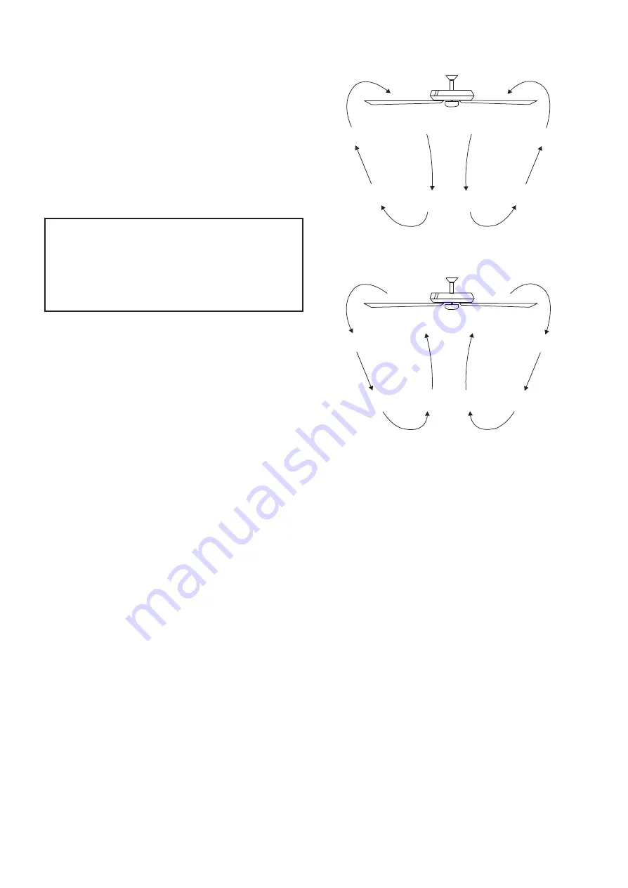
Figure 18

Figure 19

Warm weather - (Counter-Clockwise direction) A 
downward airflow creates a cooling effect as shown 
in Fig. 18. This allows you to set your air conditioner  
on a warmer setting  without  affecting your comfort. 

Cool weather - (Clockwise direction) An upward 
airflow moves warm air off the ceiling area as 
shown in Fig. 19. This allows you to set your 
heating unit on a cooler  setting without affecting 
your comfort.

NOTE:

 FAN MUST BE INSTALLED AT A 

MAXIMUM DISTANCE OF 30 FEET FROM 
THE TRANSMITTING UNIT FOR PROPER 
SIGNAL TRANSMISSION BETWEEN THE 
TRANSMITTING UNIT AND THE FAN'S 
RECEIVING UNIT.

Summary of Contents for Elise

Page 1: ...Read and Save These Instructions Weight of Fan 9 7 Kgs Elise 52 CEILING FAN INSTALLATION AND OPERATION INSTRUCTION Customer Service number 1 877 898 1881 ...

Page 2: ...oding or peeling Brass finish fans maintain their beauty when protected from varying weather conditions Any glass provided with this fan is not covered by the warranty This warranty does not apply to electrical components such as capacitors this may be damage due to fluctuation or variation of voltage Also pull chain switch for fan and light are not coved in this warranty You may call our customer...

Page 3: ... set 5 g Light kit h Light kit stem i Glass shade j Receiver 6 wire nuts k Transmitter holder 2 mounting screws l 9 Volt battery m 40W candelabra Bulbs 3 n Package hardware 1 Mounting hardware wood screws 2 screws 2 lock washers 2 washers 2 star washers 2 wire nuts 3 2 Blade attachment hardware screws 16 fiber washers 16 3 Balance Kit Philips screwdriver Straight slot screwdriver Step ladder Wire ...

Page 4: ... objects in the path of the blades 9 To avoid personal injury or damage to the fan and other items be cautious when working around or cleaning the fan 10 Do not use water or detergents when cleaning the fan or fan blades A dry dust cloth or lightly dampened cloth will be suitable for most cleaning 11 After marking electrical connections spliced conductors should be turned upward and pushed careful...

Page 5: ...g weight of the fan at least 50 lbs Do not use plastic outlet boxes Figures 1 2 and 3 are examples of different ways to mount the outlet box Note You may need a longer downrod to maintain proper blade clearance when installing on a steep sloped ceiling Fig 3 To hang your fan where there is an existing fixture but no ceiling joist you may need an installation hanger bar as shown in Figure 4 Outlet ...

Page 6: ...ews from the top of the motor assembly Step 6 Route wires exiting from the top of the fan motor through the collar cover canopy cover and canopy then through the ball downrod Fig 7 Step 7 Align the holes at the bottom of the downrod with the holes in the collar on top of the motor housing Fig 7 Carefully insert the hanger pin through the holes in the collar and downrod Be careful not to jam the pi...

Page 7: ...or Light from the receiver Secure the wire connections with the plastic wire nuts provided 3 Figure 11 Receiver to House Supply Wires Electrical Connections Connect the black hot wire from the ceiling to the black wire marked AC in L from the receiver Connect the white neutral wire from the ceiling to the white wire marked AC in N from the receiver Secure the wire connections with the plastic wire...

Page 8: ...ARNING MAKE SURE THE TAB ON THE HANGING BRACKET PROPERLY SITS IN THE GROOVE IN THE HANGER BALL BEFORE ATTACHING THE CANOPY TO THE BRACKET BY TURNING THE HOUSING UNTIL IT DROPS INTO PLACE 8 ATTACHING THE FAN BLADES Step 1 Attach the blades to the blade brackets using the screws and fiber washers provided as shown in Figure 13 Start a screw into the bracket but do not tighten Repeat for the other 2 ...

Page 9: ...se to the mounting ring and proceed to do the wire connections Connect the white wire connectors from the light kit and fan follow the same procedure with the black wire connectors Fig 14 Step 3 Place the light plate key holes over the 2 screws previously loosened from the mounting ring turn light kit until it locks in place at the narrow section of the key holes secure by tightening the 2 screws ...

Page 10: ...ght key has an auto resume it will stay at the same brightness as the last time it was turned off The Reverse switch is located on the top of the motor housing Reverse the switch to the Left for warm weather operation Slide the switch to the Right for cool weather operation Speed settings for warm or cool weather depend on factors such as the room size Ceiling height number of fans and so on NOTE ...

Page 11: ...nal protection and enhanced beauty Cover small scratches with a light application of shoe polish 4 There is no need to oil your fan The motor has permanently lubricated bearings IMPORTANT MAKE SURE THE POWER IS OFF AT THE ELECTRICAL PANEL BOX BEFORE YOU ATTEMPT ANY REPAIRS REFER TO THE SECTION MAKING ELECTRICAL CONNECTIONS Figure 18 Figure 19 Warm weather Counter Clockwise direction A downward air...

Page 12: ... ceiling It should not touch the ceiling 1 This unit is equipped with a wattage limiting device Lamping in excess of 190 watts will disable your ceiling fan s light kit To reset your light kit you must turn the power off and re lamp keeping the wattage under 190 watts Restore power to your ceiling fan and continue normal operation 1 Do not connect the fan with wall mounted variable speed control s...

Reviews: