background image


SIMRET 4000 INSTRUCTIONS 

GETTING STARTED 

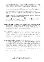
The Simret 4000 is operated by a single 

Click

 control. The central OK button may be 

single-clicked

double-clicked

, or 

held-down

. The surrounding arrow buttons are used to navigate menus by 

moving a 

 highlight

  bar


through a menu of options on the instrument’s display screen. Clicking the 

OK will select the highlighted item. Normally this will be accompanied by a beep from the 
instrument. The scroll bar on the right hand side indicates the relative position of the item within the 
menu. 
Whenever possible the instrument operates to these simple rules:  


single-click

 to choose a menu item 


single-click

 to return 


double-click

 to enter a 2

nd

 level menu  


single-click

 to return 


hold-down

 (for more than one second) to abandon a course of action  


Use

 or 

 to increase or decrease a value.  


Use the arrow buttons to scroll through a menu 


the last option of a menu will return you to the previous menu, or use the

 button. 


SWITCHING ON:

 To power the instrument, 

hold-down

 OK and then release. The display will 

appear when OK is released. The instrument will perform a short self-test and display its 
software version and when calibration is next due. The 

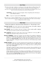
Start Menu

 will then appear.  


The self-test will warn if re-calibration is overdue and if more than 80 tests have been stored 
in memory. Upload or print the tests if the memory is getting full, then erase to create more 
space. If the SD card is fitted, tests will be backed-up automatically to create space. 

SWITCHING OFF:

 To manually switch off,

 hold-down

 OK in the 

Main Menu. 

If the control has 

not been operated for about 4 minutes, the instrument will switch itself off unless it has been 
armed for a test. It will also turn off if its battery is very low.  

EDITING: 

A built-in editor allows certain number values, names and software switches to be edited 

in the instrument. First highlight the item then for: 


Simret 4000 Instructions, Issue 10, Jan 2011 

© 1994-2011, Turnkey Instruments Ltd. Page 1 of 17 

Summary of Contents for Simret 4000

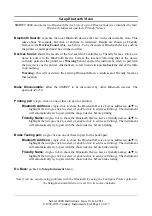
Page 1: ...f a menu will return you to the previous menu or use the button SWITCHING ON To power the instrument hold down OK and then release The display will appear when OK is released The instrument will perform a short self test and display its software version and when calibration is next due The Start Menu will then appear The self test will warn if re calibration is overdue and if more than 80 tests ha...

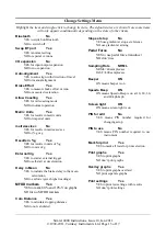
Page 2: ...ying to pair until the device is switched on and pairing is successful Successful pairing normally takes just a few seconds although if many discoverable Bluetooth or WiFi devices are in range it may take a little longer If the device will not pair just single click to try again or hold down and release to abandon and investigate To pair with the Printer first make sure the printer is switched on ...

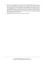
Page 3: ... connector with the cable provided the SIMRET will not make any attempt to pair using Bluetooth In this case after arming for a test just depress the pedal to trigger the instrument RE CALIBRATION Your Simret 4000 is a precision instrument and must be recalibrated annually by an accredited laboratory This gives you the optimum re assurance that the brake ratio measurements will always be accurate ...

Page 4: ...btained when the instrument base is parallel to the road surface The instrument is best used with the Pedal Pad attached to the brake pedal This informs the instrument when the brakes are applied so it can then measure the delay time of the braking system This is the time interval between applying the brakes and the deceleration start threshold being reached For heavy vehicles this may be quite si...

Page 5: ...n the instrument will try to force you to confirm the ground slope at the end of the test It has to do this because it doesn t know the proper direction of the slope until after the test You can override this by selecting NO for slope at stop during the arming menu in which case the instrument will assume it is positioned in the vehicle exactly parallel to the ground Over the years Turnkey has pro...

Page 6: ...tions single click to show a list of up to 16 site conditions or user notes to highlight then click again to select or double click to edit Measure GRADIENT single click to measure the slope gradient The instrument continuously measures and displays the slope gradient in percent A negative number means a downward gradient If a very accurate measurement is required first trim the instrument zeros s...

Page 7: ... you to hold the instrument on the brake while arming and also allows the instrument to determine its direction of travel but see Allow Coasting in Change Settings Until you reach a speed of 5 kph or mph you may still elect to measure the Slope at Stop and to Pause before doing so move the highlight and click ON or OFF as required see Change Settings The instrument will beep as this speed is passe...

Page 8: ...e times of the external start trigger if enabled and the start and end of deceleration Single click to close the graph and review other results Single click Print to print this test now regardless of the whether or not the test has been marked for print The printer will turn on automatically if it has been paired previously if not switch on first by pressing its button to pair Printing graphs and ...

Page 9: ...tic Backup if the SD card is fitted whenever the instrument switches off with its internal memory more than 80 full or containing more than 75 tests the internal memory will be automatically backed up to the next Folder Number on the SD Card The internal memory will then be erased This will be repeated when it is next full until all 1000 folders have been used 75 000 tests If the automatic backup ...

Page 10: ...k to accurately trim the zero readings of the instrument by following the on screen instructions Any flat surface may be used it need not be horizontal Erase all Tests single click to erase all the tests in the instrument s memory regardless of whether marked for erase or not You will be prompted to confirm Set Time and Date single click to set the time and date by following the on screen instruct...

Page 11: ...n The true stop time is the start of this time End Delay 2 5 s delay before measuring the stop point slope gradient Only if Slope at Stop has been selected Peak over 0 20 sec the minimum time the peak reading has to be sustained Dive 5 0 deg g compensation for the tilt of the vehicle in degrees tilt per g of deceleration caused by the movement of its suspension as it decelerates PFT trig 20 0 kgF ...

Page 12: ...ces The passcode is 1234 Printing pair single click on one of these to pair for printing Bluetooth Address single click to show the Bluetooth Device List as addresses to highlight then single click to select or double click to edit see Editing The instrument will automatically try to pair with the chosen device before printing Friendly Name single click to show the Bluetooth Device List as friendl...

Page 13: ...nits of g External trig Yes YES to start at external trigger NO to self start at deceleration Delay in Mean No YES to include the brake delay in the mean calculation NO to exclude gives higher readings MFDD markers Yes YES to mark 80 and 10 V on graphs NO for no MFDD markers Calc Distance Yes YES to calculate stopping distance NO do not calculated Slope at stop No YES use gradient at stop as refer...

Page 14: ...f you have selected Auto Alignment the instrument will force you to confirm the slope of the ground at the end of the test for it doesn t know the axis for measurement until after the test has begun Effectively Auto Alignment sets Slope at Stop ON if Brake Effort is being measured Allow Coasting is mainly for railway use and is only available if Auto Alignment is off and the External Trigger is se...

Page 15: ...as the mean deceleration between 80 and 10 of the test speed and is now used internationally as the standard measure of brake performance When MFDD markers is on marker lines are placed on the graphs at the 80 V and 10 V points These are in addition to the graph marker lines at the start and stop deceleration thresholds and the external trigger point Note if brake effort is being measured the Mean...

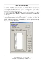
Page 16: ...If your PC is equipped with a Turnkey Bluetooth Adaptor the instrument will be discovered by it and a wireless connection made whenever it is switched on and discoverable e g in the Start Menu and Main Menu Alternatively use a Turnkey USB Link to physically connect the instrument s DIN connector to a USB port on your computer The instrument will sense the DIN connector and override the Bluetooth i...

Page 17: ... shown at the bottom of the page Click Export to download the selected page of information to the instrument Click Import to upload existing information from the instrument Click Save to save the page of information to your Windows directory for future use for example if you want to download the same plant list to several instruments Note that each tabbed page must be exported or imported and save...

Reviews: