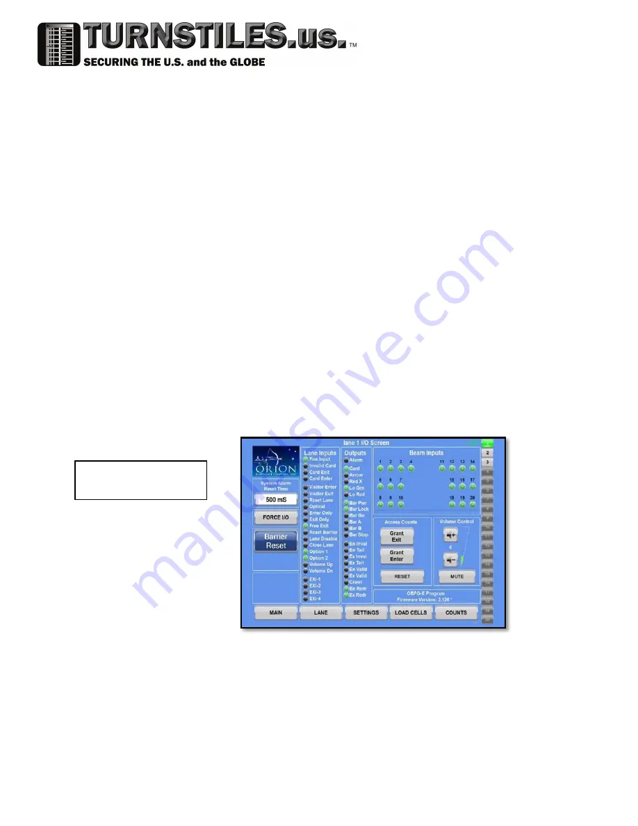
background image

 [15] 

Lane I/O Diagnostic 
Screen 

1. Visitor Entry: Pressing this button allows one person at a time to enter through

the designated lane in the entrance direction.

2. Visitor Exit: Pressing this button allows one person at a time to exit through the

designated lane in the exit direction.

3. Optical Mode: Latching this button causes the barriers to move into the disabled

position (open) and remain there during operation, while still allowing the lane to
function normally. Card access is still required.

4. Barrier Reset: Latching this button removes power to the motors. Depressing this

button will cause the barriers to recalibrate and reset their position. The lane will
be down for 25 seconds during this calibration.

5. Disable: This lane can be shut down allowing for free access in both directions.

The feature may be used for large visitor parties to pass or for maintenance/repair
by pressing this button.  Both LSIs will display a green arrow for free entry and exit.

The green LED on the pushbutton will indicate disable is active.

6. Reset: Pressing this button will shut down the alarm sounding in the specific lane.

The green LED indicates this lane is in alarm.

The Lane I/O Diagnostic screen provides Real time status of all lane inputs, outputs and 

sensor beams, as well as provides remote lane control, volume level adjustment, current 
firmware display and access to other interactive pages. 

www.TURNSTILES.us / www.entrapass.com / 8641 S. Warhawk Road, Conifer, CO 80433 / 303-670-1099

Summary of Contents for OBSG-HG

Page 1: ...1 Optical Barrier Swing Glass High Glass Clear View OBSG HG Installation Manual www TURNSTILES us www entrapass com 8641 S Warhawk Road Conifer CO 80433 303 670 1099...

Page 2: ...ry Side Electronics 7 C Lane Status Indicator LSI and Reader Mounting 8 5 WIRING 8 A Single Lane 8 B Multiple Lanes 9 C Standard Power Supply 9 D PIO to SIO Communications 10 E Motor to Motor Communic...

Page 3: ...ERS RLC optional 13 A Push Button Controller RCL PB 13 B Remote Screen Controller RLC TS or Infinity RLC SW 14 16 7 SENSOR ALIGNMENT GUIDE www TURNSTILES us www entrapass com 8641 S Warhawk Road Conif...

Page 4: ...to insure a smooth and problem free installation Here are a few pointers to keep in mind during installation 1 Beam alignment is critical The physical layout and securing of the speedgate to the floo...

Page 5: ...referenced from the unsecured side of the building Pedestal 1 will always be the turnstile farthest to the right Pedestal 2 will be just to the left of Pedestal 1 and so forth These pedestal numbers...

Page 6: ...n the primary side of the lane Alarm Speaker One speaker is mounted above the PIO and produces the sound for each lane Mini Master Motor Controller The mini master is used as a language translator bet...

Page 7: ...well as saves all of the settings for each lane Chopper Board Resistor This board is in line with the direct motor power It is used to direct any generated power from the movement of the arms into th...

Page 8: ...alled in the field at a later date If a non standard proximity card reader is used 5 WIRING A Single Lane One OBSG HG CV speedgate consists of two pedestals Each lane will contain one 1 Primary I O Bo...

Page 9: ...ly 120Vac 24Vdc 10A Power Supply Verify output power is between 24 25VDC on two pin connector J11 before connecting it to PIO The Life Safety power supply provided with the units is capable of handlin...

Page 10: ...rom each lane s primary pedestal PIO to the corresponding lane s secondary pedestal SIO 24vdc Input for the PIO Board Connector J11 Connect pins 1 4 from J12 on the PIO board to J1 on the SIO Board PI...

Page 11: ...wered the green LED on the motors should be solid if it is blinking the communications cable is not seated properly F Access Control FACP Inputs An 18awg 6 conductor is required to run to each lane s...

Page 12: ...t simply provide a jumper from that point to ground 22 14 from RLC PB to PIO Board Connector J16 Listed From bottom to top Point Description 16 Visitor Enter 15 Visitor Exit 14 Reset Lane 13 Optical M...

Page 13: ...uter a separate cable should be run from the DHCP device to the control computer IPs will need to be saved to each PIO and then set in the computer J Earth Ground An earth ground is required to each p...

Page 14: ...on our standard touchscreen computer RLC TS or our Surface Pro bundle RLC SP The Main Control Screen is customizable for viewing all the lanes in your suite at one time It provides visitor entry exit...

Page 15: ...eir position The lane will be down for 25 seconds during this calibration 5 Disable This lane can be shut down allowing for free access in both directions The feature may be used for large visitor par...

Page 16: ...r vertically should be done by loosening one of the screws that mount the sensor to the sensor bracket adjusting and then tightening in place 5 During adjustments look for the orange LED on top of the...

Reviews:

Related manuals for OBSG-HG