background image

 [11] 

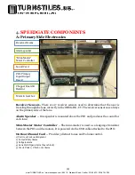
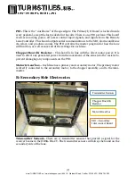
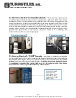
E: Motor to Motor Communications –


Each lane has a primary and

secondary  motor.  These  motors  need  to  communicate  with  each  other  via  a  direct 
connection. There is a cable coiled up in pedestal 1 that will need to be attached to the 
motor in pedestal 2. If there are multiple lanes in the suite, pedestal 2 will have a cable 

coiled inside that will attach to the motor in pedestal 3, etc. The motors closest to each 
other in the lane should be connected. Verify that the primary motor of lane 1 and the 

primary  motor  of  lane  2  are  not  accidently  connected  together.  When  the  lane  is  fully 
powered  the  green  LED  on  the  motors  should  be  solid;  if  it  is  blinking,  the 
communications cable is not seated properly.   

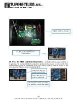
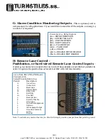
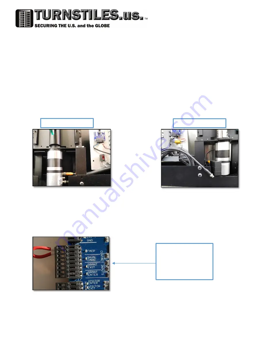
F: Access Control / FACP Inputs

 – An 18awg /6 conductor is required

to run to each lane’s PIO in order to operate the lanes in both directions and provide the 

Invalid Card Alarm Signal.  Each access point should be a dry contact closure of 1 second 
or less
 from your access control system relays. Provide a separate isolated 18awg 
/2 conductor stranded fire rated cable to a N/C fire alarm relay. This input 

may not be in series or parallel with any other device. 

18/6 to PIO board 

Connector J17:  

Grant Enter = 1&2 

Grant Exit = 3&4 

Invalid Card = 5&6 
FACP = 7&8 

Secondary side motor 

Primary side motor 

www.TURNSTILES.us / www.entrapass.com / 8641 S. Warhawk Road, Conifer, CO 80433 / 303-670-1099

Summary of Contents for OBSG-HG

Page 1: ...1 Optical Barrier Swing Glass High Glass Clear View OBSG HG Installation Manual www TURNSTILES us www entrapass com 8641 S Warhawk Road Conifer CO 80433 303 670 1099...

Page 2: ...ry Side Electronics 7 C Lane Status Indicator LSI and Reader Mounting 8 5 WIRING 8 A Single Lane 8 B Multiple Lanes 9 C Standard Power Supply 9 D PIO to SIO Communications 10 E Motor to Motor Communic...

Page 3: ...ERS RLC optional 13 A Push Button Controller RCL PB 13 B Remote Screen Controller RLC TS or Infinity RLC SW 14 16 7 SENSOR ALIGNMENT GUIDE www TURNSTILES us www entrapass com 8641 S Warhawk Road Conif...

Page 4: ...to insure a smooth and problem free installation Here are a few pointers to keep in mind during installation 1 Beam alignment is critical The physical layout and securing of the speedgate to the floo...

Page 5: ...referenced from the unsecured side of the building Pedestal 1 will always be the turnstile farthest to the right Pedestal 2 will be just to the left of Pedestal 1 and so forth These pedestal numbers...

Page 6: ...n the primary side of the lane Alarm Speaker One speaker is mounted above the PIO and produces the sound for each lane Mini Master Motor Controller The mini master is used as a language translator bet...

Page 7: ...well as saves all of the settings for each lane Chopper Board Resistor This board is in line with the direct motor power It is used to direct any generated power from the movement of the arms into th...

Page 8: ...alled in the field at a later date If a non standard proximity card reader is used 5 WIRING A Single Lane One OBSG HG CV speedgate consists of two pedestals Each lane will contain one 1 Primary I O Bo...

Page 9: ...ly 120Vac 24Vdc 10A Power Supply Verify output power is between 24 25VDC on two pin connector J11 before connecting it to PIO The Life Safety power supply provided with the units is capable of handlin...

Page 10: ...rom each lane s primary pedestal PIO to the corresponding lane s secondary pedestal SIO 24vdc Input for the PIO Board Connector J11 Connect pins 1 4 from J12 on the PIO board to J1 on the SIO Board PI...

Page 11: ...wered the green LED on the motors should be solid if it is blinking the communications cable is not seated properly F Access Control FACP Inputs An 18awg 6 conductor is required to run to each lane s...

Page 12: ...t simply provide a jumper from that point to ground 22 14 from RLC PB to PIO Board Connector J16 Listed From bottom to top Point Description 16 Visitor Enter 15 Visitor Exit 14 Reset Lane 13 Optical M...

Page 13: ...uter a separate cable should be run from the DHCP device to the control computer IPs will need to be saved to each PIO and then set in the computer J Earth Ground An earth ground is required to each p...

Page 14: ...on our standard touchscreen computer RLC TS or our Surface Pro bundle RLC SP The Main Control Screen is customizable for viewing all the lanes in your suite at one time It provides visitor entry exit...

Page 15: ...eir position The lane will be down for 25 seconds during this calibration 5 Disable This lane can be shut down allowing for free access in both directions The feature may be used for large visitor par...

Page 16: ...r vertically should be done by loosening one of the screws that mount the sensor to the sensor bracket adjusting and then tightening in place 5 During adjustments look for the orange LED on top of the...

Reviews: