OPERATING INSTRUCTIONS
11/26/2019
6
Installation
Securely mount the heater before wiring.
▪
WARNING
: THE INLET AIR/GAS SIDE OF THE HEATER IS THE PLASTIC HOUSING END WHERE THE
POWER TERMINALS AND THERMOCOUPLE TERMINAL BLOCK IS LOCATED. INSTALLING THE
HEATER IN THE WRONG ORIENTATION WILL DAMAGE THE HEATER AND CAN CREATE
ADDITIONAL HAZARDS AS A RESULT. POWER CONNECTION WIRE SIZES ARE RECOMMENDED IN
THE PRODUCT TABLE ABOVE. THESE ARE RECOMMENDATIONS ONLY, AND ALL LOCAL AND
REGIONAL ELECTRICAL CODES SHOULD BE CONSULTED.
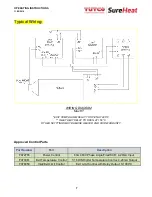
The following is a typical and recommended setup for the Max
HT Heater. The Type “K” thermocouple sensors
mounted outside the Max HT provide flexibility and safety for use with various control systems.
➢
Wire heater according to WIRING DIAGRAM shown. Follow applicable electrical codes when mounting and
wiring system.
➢
The configuration shown is recommended by TUTCO SureHeat for safe and optimum performance.
1. Note THREE (3) control devices are required for proper and safe heater operation, and should be mounted in an
appropriate control cabinet:
i.
MAIN TEMPERATURE CONTROL
•
Controls the heater process temperature
•
Can be 4-
20mA output, or “Pulsed DC” output (0-10V, 3-32V, etc.)
•
Output type will depend on type of POWER CONTROL chosen.
•
Set to
1652
o
F (900°C) MAXIMUM
to prevent overshooting and element failure.
•
A low temperature test run is suggested to verify the closed loop control (PID) settings are
properly set. Overshoot and oscillating process temperature should be avoided to ensure long
heater element life. (Contact the factory for assistance if needed)
ii.
INLET PRESSURE/FLOW SWITCH CONTROL
•
Shuts the MAIN TEMP CONTROL output signal off is the heater is not supplied enough airflow.
•
The MINIMUM airflow needed to avoid damaging the heater is 18 SCFM (510 SLPM)
iii.
POWER CONTROL
•
Regulates the AC voltage to the heater.
•
Select according to heater maximum voltage, and amperage.
•
Suitable POWER CONTROL types:
1.
“Zero-Cross Solid State Relay (SSR), (Pulsed DC Input) - or –
2.
“Phase-Angle” Fired Silicon Controlled Rectifier (SCR) (4-20mA Input)
2. NOTE ON SENSOR CONNECTION
i.
Type “K” thermocouple connects to EXIT TEMPERATURE CONTROL using Type “K” thermocouple wire.
ii. Note that YELLOW is POSITIVE and RED is NEGATIVE for these Thermocouple connections.
3. NOTE ON POWER CONNECTIONS (L1, L2, L3, H1, H2, H3)
Power connection wire sizes are recommended in the Heater Models and Parts List located on page 3. These are
recommendations only, and all local and regional electrical codes should be consulted.
i. LINE TO POWER CONTROL Fuses must be appropriately sized for maximum heater current.
4. NOTE ON TEMPERATURE CONTROLS
i. The AC power source should be taken from the incoming line power (transformed as appropriate).
ii. The AC power source to the Temperature Controls should be energized simultaneously with power to the
Power Control. This is usually done via circuit breaker or power disconnect switch on main control
cabinet.


