background image

O P E R A T I N G   M A N U A L

Serpentine II

 and Serpentine VI 

Air Heaters

Summary of Contents for Serpentine II

Page 1: ...O P E R A T I N G M A N U A L Serpentine II and Serpentine VI Air Heaters ...

Page 2: ...tages from 2000 to 3600W and the Serpentine VI wattages from 5000 to 8000W If operated correctly element life will be greater than 5000 hours SERPENTINE HEATER SPECIFICATIONS Maximum Inlet Air Pressure 25 PSI 1 7 BAR Maximum Inlet Air Temperature 200 F 93 C Maximum Exit Air Temperature 1400 F 760 C Single Stage 1500 F 815 C Two Stage see page 10 for Performance Curves Minimum Airflow Recommended 6...

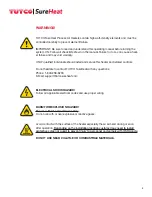
Page 3: ...ls Do not hesitate to contact TUTCO SureHeat with any questions Phone 1 800 258 8290 E Mail support tutcosureheat com ELECTRICAL SHOCK HAZARD Follow all applicable electrical codes and use proper wiring BURN FIRE EXPLOSION HAZARD For use with Air or Inert Gases Only Do not use with or near explosive or reactive gases Avoid contact with the surface of the heater especially the air exit end during o...

Page 4: ...e TC holder F040299 TC Holder mounted on exit of F057088 Housing Assembly Use of other sensor types and or locations can result in heater damage if used for process control Minimum airflow for accurate control is 120 SCFH 57 SLPM Maximum air temperature is as listed in table above Operating above this will void warranty Part Number F029765 F029766 F029767 F060418 Maximum Watts 2000 2800 3600 3600 ...

Page 5: ...tine VI Elements Housing Exchanger 5 A 7 69 195mm 8 13 206mm B 7 69 195mm 8 13 206mm C 0 63 16mm 0 63 16mm A 10 25 260mm B 10 88 276mm C 1 25 32mm Part Number Serpentine II F029763 Serpentine VI F057088 A 9 63 245mm 12 38 314mm B 0 70 Ø 18mm 1 38 Ø 35mm C 1 50 Ø 38mm 2 12 Ø 54mm D 1 00 25mm 1 00 25mm E 0 38 9 5mm 0 50 13mm Air Inlet FNPT 0 375 9 5mm 0 750 19mm Part Number F040291 5 0kW F040292 6 0...

Page 6: ...ent will overheat very quickly and burn out NOTE A thermocouple cannot detect temperatures if there is no flow turn on flow before applying power even when a controller with a thermocouple is being used 4 Use phase angle fired power controllers On off controllers may shorten heater life or burnout element 5 For closed loop control use exposed junction type K thermocouple within one inch of the hea...

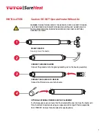
Page 7: ...rom the heater exit Tutco SureHeat recommends using an exposed junction type K thermocouple like Part F039272 Contact Tutco SureHeat for specifications MOUNT HEATER Securely mount the heater 1 2 3 4 WARNING THE INLET AIR GAS SIDE OF THE HEATER IS LOCATED CLOSEST TO WHERE THE POWER FEED THRU CONNECTIONS ARE MADE INSTALLING THE HEATER IN THE WRONG ORIENTATION WILL DAMAGE THE HEATER AND CAN CREATE AD...

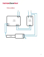
Page 8: ...TYPICAL WIRING AC AC L1 L2 L1 H1 TC TC Output Temp Control Power Control Heater H1 H2 G 8 ...

Page 9: ... 5 CONTROL AIRFLOW Ensure airflow is on before voltage is applied to heater The heater should NOT be operated with an airflow of less that 1 SCFM or 60 SCFH may cause the heater s element to overheat too quickly and burnout 6 CLOSED OR OPEN LOOP SYSTEM If using a closed loop system turn on power to the temperature and power controller then set the desired temperature on the temperature controller ...

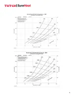
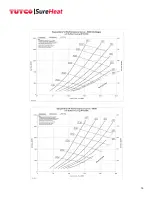
Page 10: ...fe normal life operating conditions The shorter dash lines indicate marginal shorter life operating conditions leading to premature burnout With a known flow or pressure at the heater entrance follow the flow or pressure line across until it meets the desired temperature curve Drop a line straight down to intersect the x axis This point along the Heater volts true RMS axis represents the voltage r...

Page 11: ...11 9 ...

Page 12: ...10 12 ...

Page 13: ...SERPENTINE VI ELEMENTS 13 ...

Page 14: ...14 ...

Page 15: ...15 ...

Page 16: ...out procedures a For Troubleshooting Heater i Use multi meter to check continuity between 1 Power terminals H1 to H2 2 Thermocouples positive yellow to negative red ii If there is continuity on all above tests check system wiring 1 Crossed thermocouple wires 2 Reversed thermocouple wire polarity Note RED is NEGATIVE 3 Verify inlet air temperature is below set point on INLET TEMPERATURE controller ...

Page 17: ...ing PID Proportional P Integral I and Derivative D settings as a starting point for stable temperature control Some manual tuning may be required for more precise control Description Range Default P roportional 90 250 131 I ntegral 8 20 9 D erivative 0 2 2 Scan Cycle Rate 500mSec 200mSec 4 Incorporate a Ramp Rate for the start up of the heater The slower you ramp to your final set point the less o...

Page 18: ...N LIEU OF ALL OTHER WARRANTIES EXPRESS OR IMPLIED INCLUDING WITHOUT LIMITATION ANY IMPLIED WARRANTY OF FITNESS FOR A PARTICULAR PURPOSE OR OF MERCHANTABILITY The information contained in this manual is based on data considered to be true and accurate Reasonable precautions for accuracy has been taken in the preparation of this manual however TUTCO SureHeat assumes no responsibility for any omissio...

Page 19: ...suppliedinthisoperatingmanualaresubject to change without prior notice Contact TUTCO SureHeat for additional assistance 603 418 7662 support tutcosureheat com orders tutcosureheat com 22 Industrial Drive Exeter NH 03833 USA Aerospace Automotive 3D Printing Electronics Medicine Packaging Printing Plastics Textiles ...

Reviews: