background image

Replacement Procedures 

I. Replacing the Heating Element

1.

Turn heater/blower switches OFF, and disconnect from power source.

2.

Use a flat screwdriver to remove (pry open) the wiring cover under the stainless nozzle
tube.

3.

Remove the stainless nozzle by removing the two mounting screws, and the thru-bolt
which passes through the plastic support tower and threads into the nozzle flange.

4.

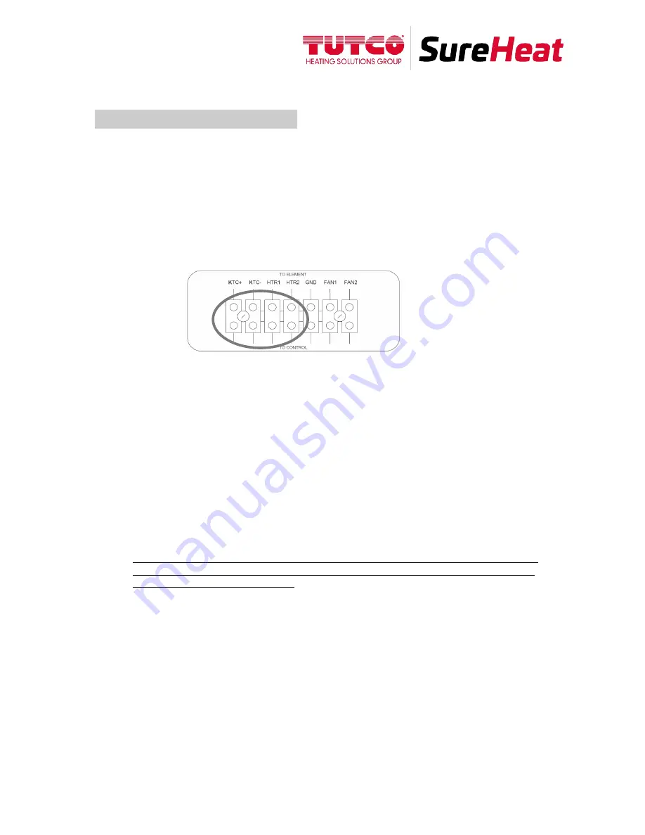
Disconnect the KTC+ (Yellow), KTC- (Red), HTR1, HTR2 connections from the wiring
terminal as shown.  Total of four wires.

5.

Remove the old element, pulling the KTC and HTR wires through the plastic support
tower.

6.

Install new element by reversing steps 2-5.

II. Replacing the Temperature Controller

1.

Turn heater/blower switches OFF, and disconnect from power source.

2.

Remove the four screws which secure the black plastic top cover plate.

3.

Remove the four screws which attach the aluminum base plate to the main heater plastic
structure.

4.

With the top cover plate and the aluminum plate removed, you now have access to the
top and bottom mounting tabs on the temperature controller.

5.

While lifting the top and bottom white plastic mounting tabs, gently push the temperature
controller halfway out of the faceplate.

6.

Using masking tape or other method, mark each wire going to the back of the controller
with a number 1-9, corresponding to its terminal location.   This is CRITICAL to ensure
proper wiring to the new controller.

7.

Using a small screwdriver, loosen and remove the wires from the terminals at the rear of
the temperature controller.

8.

Remove temperature controller completely from the faceplate.

9.

Install new temperature controller halfway into faceplate.

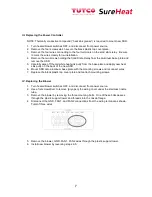
10. Reconnect the wires according to the terminal number and ID marking from step #4.
11. Press controller into faceplate while engaging the white mounting tab securely.
12. Replace the black plastic top cover plate and reattach mounting screws.

6

Summary of Contents for SKORPION F075615

Page 1: ...rical codes and use proper wiring BURN HAZARD Avoid contact with the heater nozzle during or soon after operation EXPLOSION HAZARD Heater produces extremely high temperatures Do not use in hazardous environments and or near explosive or reactive gases or combustible materials O OP PER ERAT ATIN ING G INSTRUCTIONS 2 6 2018 SKORPION Process Air Heater ...

Page 2: ...D WITH RESPECT TO THE PRODUCT INCLUDING THE IMPLIED WARRANTIES OF MERCHANTABILITY AND FITNESS FOR A PARTICULAR PURPOSE IN NO EVENT SHALL OSPI BE LIABLE FOR ANY SPECIAL INCIDENTAL OR CONSEQUENTIAL DAMAGES INCLUDING LOST PROFITS OR REVENUES OR ANY OTHER COSTS OR DAMAGES SOME STATES DO NOT ALLOW LIMITATIONS ON HOW LONG AN IMPLIED WARRANTY LASTS AND OR DO NOT ALLOW THE EXCLUSION OF INCIDENTAL OR CONSE...

Page 3: ... F205513 N A F205494 F075616 3 0kW 230V 1 Ø 13A F205502 F205499 F205486 F205512 N A F205494 F076008 4 5kW 230V 1 Ø 20A F205614 F205499 F205486 F205604 N A F205494 Complete Unit without Blower F075869 1 5kW 120V 1 Ø 12 5A F205526 F205499 F205486 N A F205549 F205494 F075835 3 0kW 230V 1 Ø 13A F205526 F205499 F205486 N A F205549 F205494 F076029 4 5kW 230V 1 Ø 20A F205614 F205499 F205486 N A F205549 F...

Page 4: ...d screw terminal Additional protective earthing can be attached to the aluminum base plate if desired Basic Operation 1 Turn SKORPION air heater ON using two switches 1 1 Switch S1 blower sends power to the blower and to heater switch S2 1 2 Switch S2 heater sends power to the heater control circuit 1 3 Note for heater safety S2 heater cannot turn ON without S1 blower ON 2 Adjust airflow via a rot...

Page 5: ...overheats bright orange color the photo detector resistance decreases which reduces the control signal which in turn limits power to the heater o If the air temperature in the housing reaches an unsafe level the thermistor resistance decreases which reduces the control signal which in turn limits power to the heater o A small fixed resistor in series with the control signal sets element and air te...

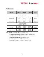
Page 6: ...750 C 1400 F 12 SCFM 340 SLPM 12 SCFM 340 SLPM 22 SCFM 623 SLPM see note FOR SKORPION models without Blower external air source A The maximum temperature capability of heater will depend entirely on the airflow rate produced by external air source Higher airflow rates than those produced by the standard SKORPION blower will yield lower maximum temperatures B External air supply must be turned ON p...

Page 7: ...ich attach the aluminum base plate to the main heater plastic structure 4 With the top cover plate and the aluminum plate removed you now have access to the top and bottom mounting tabs on the temperature controller 5 While lifting the top and bottom white plastic mounting tabs gently push the temperature controller halfway out of the faceplate 6 Using masking tape or other method mark each wire g...

Page 8: ...d apply new heat sink putty on the back of the new SSR 6 Mount SSR onto aluminum base plate with the mounting screws and reconnect wires 7 Replace the black plastic top cover plate and reattach mounting screws IV Replacing the Blower 1 Turn heater blower switches OFF and disconnect from power source 2 Use a flat screwdriver to remove pry open the wiring cover under the stainless nozzle tube 3 Remo...

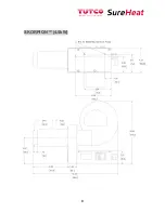
Page 9: ...SKORPION 1 5kW 3 0kW 8 ...

Page 10: ...SKORPION 4 5kW 9 ...

Page 11: ...SKORPION Without Blower 1 5kW 3 0kW 4 5kW 10 ...

Page 12: ...Tutco SureHeat 129 Portsmouth Avenue Exeter NH 03833 USA Tel 800 258 8290 support sureheat com www tutcosureheat com ...

Reviews: