background image

WARRANTY – TRUCK BLOWERS

Subject to the terms and conditions hereinafter set forth and set forth in General Terms of Sale, Tuthill Vacuum & Blower 

Systems (the Seller) warrants products and parts of its manufacture, when shipped, and its work (including installation and 

startup) when performed, will be of good quality and will be free from defects in material and workmanship. This warranty 

applies only to Seller’s equipment, under use and service in accordance with Seller’s written instructions, recommendations 

and ratings for installation, operating, maintenance and service of products, for a period as stated in the table below. Because 

of varying conditions of installation and operation, all guarantees of performance are subject to plus or minus 5% variation. 

(Non-standard materials are subject to a plus or minus 10% variation)

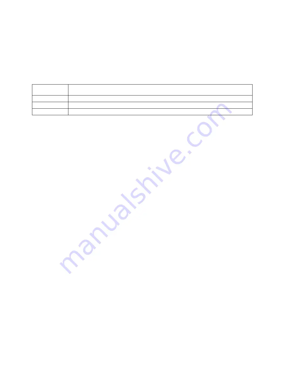
PRODUCT

TYPE

WARRANTY DURATION

New

18 months from date of shipment, or 12 months after initial startup date, whichever occurs first

Remanufactured

12 months from date of shipment, or 12 months after initial startup date, whichever occurs first

Repair

12 months from date of shipment, or remaining warranty period, whichever is greater

THIS WARRANTY EXTENDS ONLY TO BUYER AND/OR ORIGINAL END USER, AND IN NO EVENT SHALL THE SELLER 

BE LIABLE FOR PROPERTY DAMAGE SUSTAINED BY A PERSON DESIGNATED BY THE LAW OF ANY JURISDICTION 

AS A THIRD PARTY BENEFICIARY OF THIS WARRANTY OR ANY OTHER WARRANTY HELD TO SURVIVE SELLER’S 

DISCLAIMER.

All accessories furnished by Seller but manufactured by others bear only that manufacturer’s standard warranty.  

All claims for defective products, parts, or work under this warranty must be made in writing immediately upon discovery and, 

in any event within one (1) year from date of shipment of the applicable item and all claims for defective work must be made 

in writing immediately upon discovery and in any event within one (1) year from date of completion thereof by Seller.  Unless 

done with prior written consent of Seller, any repairs, alterations or disassembly of Seller’s equipment shall void warranty.  

Installation and transportation costs are not included and defective items must be held for Seller’s inspection and returned to 

Seller’s Ex-works point upon request.

THERE ARE NO WARRANTIES, EXPRESSED, IMPLIED OR STATUTORY WHICH EXTEND BEYOND THE DESCRIPTION 

ON THE FACE HEREOF, INCLUDING WITHOUT LIMITATION, THE IMPLIED WARRANTIES OF MERCHANTABILITY AND 

FITNESS OF PURPOSE.

After Buyer’s submission of a claim as provided above and its approval, Seller shall at its option either repair or replace its 

product, part, or work at the original Ex-works point of shipment, or refund an equitable portion of the purchase price.  

The products and parts sold hereunder are not warranted for operation with erosive or corrosive material or those which may 

lead to build up of material within the product supplied, nor those which are incompatible with the materials of construction. 

The Buyer shall have no claim whatsoever and no product or part shall be deemed to be defective by reason of failure to 

resist erosive or corrosive action nor for problems resulting from build-up of material within the unit nor for problems due to 

incompatibility with the materials of construction.

Any improper use, operation beyond capacity, substitution of parts not approved by Seller, or any alteration or repair by 

others in such manner as in Seller’s judgment affects the product materially and adversely shall void this warranty.  

No employee or representative of Seller other than an Officer of the Company is authorized to change this warranty in any 

way or grant any other warranty. Any such change by an Officer of the Company must be in writing.

The foregoing is Seller’s only obligation and Buyer’s only remedy for breach of warranty, and except for gross negligence, 

willful misconduct and remedies permitted under the General Terms of Sale in the sections on CONTRACT PERFORMANCE, 

INSPECTION AND ACCEPTANCE and the PATENTS Clause hereof, the foregoing is BUYER’S ONLY REMEDY 

HEREUNDER BY WAY OF BREACH OF CONTRACT, TORT OR OTHERWISE, WITHOUT REGARD TO WHETHER ANY 

DEFECT WAS DISCOVERED OR LATENT AT THE TIME OF DELIVERY OF THE PRODUCT OR WORK. In no event shall 

Buyer be entitled to incidental or consequential damages. Any action for breach of this agreement must commence within 

one (1) year after the cause of action has occurred.

January 2005

Summary of Contents for T1050

Page 1: ...thill Vacuum Blower Systems tuthillvacuumblower com 800 825 6937 WARNING Do Not Operate Before Reading Manual Operator s Manual Tuthill T850 T1050 Standard Weight Rotary Positive Displacement Truck Blower Copyright 2017 Tuthill Vacuum Blower Systems All rights reserved Product information and specifications subject to change ...

Page 2: ...specifications to explain and or exemplify a product service or maintenance improvement may be changed at any time without notice Rights Reserved Statement No part of this publication may be reproduced or used in any form by any means graphic electronic or mechanical including photocopying recording taping or information storage and retrieval systems without the written permission of Tuthill Vacuu...

Page 3: ...structions 3 Safety Precautions 3 Installation 5 Safety Checklist 5 Specifications 6 Outline Drawings 7 PTO Selection for Transmission 8 Engine Speed 8 Pressure Relief Valve 8 Air Filter 8 Suction and Discharge Piping 8 Mounting Bracket 8 Check Valve 8 Mufflers and Discharge Filtration 8 Vacuum Valve 9 Performance Curves 10 ...

Page 4: ...nce 14 Regular Maintenance 14 Disassembly and Reassembly 15 Disassembly 15 Assembly 16 Gear End Assembly 16 Drive End Assembly 17 Checking Interlobe Clearance 18 Assembly Clearances 20 Special Tool Drawings 21 Assembly Drawing and Parts List 23 Assembly Drawing 23 Parts List 24 Blower Installation Components 25 ...

Page 5: ... If the blower is stored outdoors be sure to protect it from weather and corrosion Tuthill Truck Blowers are built to exacting standards and if properly installed and maintained will provide many years of reliable service Read and follow every step of these instructions when installing and maintaining the blower OTE N Record the blower model and serial numbers of the machine in the OPERATING DATA ...

Page 6: ...ry CAUTION Indicates a hazardous situation that if not avoided could result in minor or moderate injury Indicates a situation that can cause damage to the engine personal property and or the environment or cause the equipment to operate improperly OTE N Indicates a procedure practice or condition that should be followed in order for the equipment to function in the manner intended CAUTION Read man...

Page 7: ...may require ear protection Blower heat can cause burns if touched Safety Precautions For equipment covered specifically or indirectly in this operator s manual it is important that all personnel observe safety precautions to minimize the chances of injury Among many considerations the following should particularly be noted Rotating shafts can be dangerous You can snag clothes skin hair hands etc T...

Page 8: ...s If you use worn out or damaged drive line components If you use drive line components in a non approved application This manual contains safety instructions Read understand and follow this manual Get proper training Learn and follow safe operating procedures Use proper tools and safety equipment Use proper components in good condition ...

Page 9: ...rs secured Ensure PTO rotates blower in the correct direction indicated by arrow Ensure air inlet filter is connected and located away from truck exhaust Remove Camlock dust cap and discharge piping open to atmosphere With tractor engine at idle slowly engage PTO Check for correct rotation Slowly bring blower up to operating speed Check for vibration mechanical noise oil leaks and mounting integri...

Page 10: ... MAXIMUM PRESSURE MAXIMUM VACUUM RPM RANGE T850 225 565 CFM 527 1 700 m h 20 psig 1 37 bar g 17 inch Hg 575 Mbar 1 000 3 000 T1050 450 1 200 CFM 764 2 039 m h 18 psig 1 24 bar g 17 inch Hg 575 Mbar 1 450 3 000 OTE N Reduce the maximum operating pressure by 1 psi 0 068 bar for each 2 000 feet 610 m of elevation above sea level Example At an altitude of 4 000 feet 1 219 m the maximum working pressur...

Page 11: ...er Distributor Dimensions are shown in inches and millimeters 68 133 68 75 58 149 456 76 576 317 298 640 349 308 OIL FILL LOCATION HORIZONTAL AIR FLOW OIL LEVEL GAUGE VERTICAL AIR FLOW OIL FILL LOCATION VERTICAL AIR FLOW OIL DRAIN HORIZONTAL AIR FLOW A B C 8 1 2 13 UNC 2 68 5 25 2 68 2 94 2 28 3 8 KEY Ø 1 625 8 5 8 11 UNC A B C 5 86 17 97 3 22 69 12 48 11 72 25 19 13 73 12 13 T850 MODEL T1050 Figu...

Page 12: ...is can cause the blower to overheat causing irreparable damage AIR FILTER Select a filter suitable for the air flow requirement of the application Use air filters on food and plastic products to prevent contamination An undersized air filter will cause the blower to operate at higher temperatures This can cause blower to overheat causing irreparable damage SUCTION AND DISCHARGE PIPING All piping s...

Page 13: ...nlet filter This valve is normally mounted on the trailer To properly protect the blower from overheating when vacuum loading install a vacuum valve DISCHARGE LEFT DRIVE INTAKE DISCHARGE INTAKE DISCHARGE DISCHARGE INTAKE BOTTOM DRIVE CW ROTATION CW ROTATION CCW ROTATION VERTICAL FLOW HORIZONTAL FLOW INTAKE TOP DRIVE Figure 3 2 Flow Direction and Rotation ...

Page 14: ... 750 1000 1250 1500 1750 2000 2250 300 400 500 600 700 800 900 1000 AIRFLOW AT INLET CFM 0 150 300 450 600 750 900 1050 1200 1350 0 150 300 450 600 750 900 1050 1200 1350 50 75 100 BHP 0 25 50 75 100 BHP 0 10 20 30 40 50 60 70 80 KW 0 5 10 15 20 25 KW 0 5 10 15 20 25 30 KW 0 10 20 30 40 50 60 70 KW 0 10 20 30 40 50 60 BHP 0 15 30 45 60 75 90 105 120 BHP AIRFLOW BASED UPON INLET CONDITIONS OF 14 7 ...

Page 15: ... 1 Remove the fill plugs from both gear end and drive end plates 2 Slowly pour oil through fill until oil appears in the oil sight glass Bring the oil level to the center of the sight glass 3 Verify the oil level is at the proper level in both the gear end and drive end sight glasses 4 Replace the fill plugs that were removed in step 1 Never mix oil types or grades in a Tuthill Truck Blower Mixing...

Page 16: ...il than what is included with the blower will be needed for installation Tuthill PneuLube is available from your authorized Tuthill Truck Blower Distributor Figure 3 4 Oil Fill Locations HORIZONTAL AIR FLOW STANDARD VERTICAL AIR FLOW OPTIONAL Drive end 0 75 qt 0 71 L 1 2 qt 1 1 L Non drive gear end 0 63 qt 0 60 L 1 1 qt 1 0 L Table 3 2 Lubrication Capacities OTE N Oil capacities are based on filli...

Page 17: ...cturer s recommendation Do not exceed the maximum tank pressure 6 While discharging visually check the blower for vibration mechanical noise or excessive heat 7 If the relief valve is opening adjust the proportioning valve to reduce the tank pressure 8 Reduce pressure to zero as per the trailer manufacturer s instructions 9 Disengage PTO No cool down period is required 10 Disconnect the blower hos...

Page 18: ...g is recommended as a minimum maintenance program An oil analysis program is recommended DAILY WEEKLY MONTHLY SEMIANNUALLY 1 Check and maintain oil level and add oil as necessary 2 Check air filter restriction indicator 1 Clean the air filter A clogged air filter can seriously affect the efficiency of the blower and cause overheating and oil usage 2 Check the relief valve to make sure it is operat...

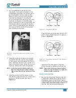
Page 19: ...end Remove the timing gear from the rotor shaft by using a gear puller see Figure 6 1 Rotate the timing gear to the right and left 3 teeth each direction from the timing marks on the face of the gears as the gear is being removed Inspect the gear teeth for wear and pitting Inspect the rotor shaft keyway for wear and damage 1 2 5 8 5 1 4 2 15 16 1 7 8 3 4 Drill Ø 11 16 Tap 3 4 16 UNF 7 16 1 Slot Th...

Page 20: ... Assembly 4 Gasket 2 Drive Shaft Seal 1 O Ring 2 Port Gasket 2 Timing Adjustment Shim 1 Bearing Shim 8 Table 6 1 Overhaul Kit Gear End Assembly 1 Check all parts to make sure the parts are clean and free of burrs or nicks that may have occurred when the blower was being disassembled Check the repair kit for the correct parts needed to complete the assembly of the unit Make sure you have the proper...

Page 21: ...securely Check the gear end clearance between the rotors and end plate OTE N Install the bearing retaining washer at this time if the blower requires retainers Then check the gear end clearance of the unit 6 Install the gear key into the keyway of each rotor Make sure the keyways are in the correct position for the timing gears as shown in Figure 6 4 Drive Gear Driven Gear Figure 6 4 Timing Marks ...

Page 22: ...he shaft 5 Install O ring into drive end cover Install the drive cover onto the extension cover Tighten the cover securely to cover the extension Install the drive shaft seal into the drive cover Figure 6 7 Extension Cover Installed Drive End 6 Install the pipe plugs and oil sight glasses into their proper locations which are determined by the direction of flow of the blower When installing drive ...

Page 23: ...ecord along with gear end and drive end clearances Tip dowel location is when the tip of the rotor is lined up with the dowel pins in the housing Check the clearance as close to the dowel as possible Long Feeler Gauge Record B B Reading Here Record A A Reading Here A A A A B B B B A A A A B B B B Figure 6 8 Checking Interlobe Clearance 2 Install the rotor washer and bolt on the gear end rotor shaf...

Page 24: ... 0 004 0 009 in 0 10 0 23 mm 0 013 0 018 in 0 33 0 46 mm 0 021 0 022 in 0 53 0 56 mm 0 013 0 017 in 0 33 0 43 mm 0 006 0 010 in 0 15 0 25 mm 0 003 0 007 in 0 08 0 19 mm T1050 0 004 0 009 in 0 10 0 23 mm 0 015 0 020 in 0 38 0 51 mm 0 023 0 024 in 0 58 0 61 mm 0 013 0 017 in 0 33 0 43 mm 0 006 0 010 in 0 15 0 25 mm 0 003 0 007 in 0 08 0 19 mm ...

Page 25: ...Operator s Manual 2020 0217 ENG 21 See Figure 8 1 on the following page SPECIAL TOOL DRAWINGS 8 ...

Page 26: ...9 247 7 236 2 50 8 86 5 73 0 19 1 234 2 50 8 15 9 257 2 73 0 1 5 4 0 88 8 72 4 69 9 5 1 88 9 58 4 44 5 9 5 268 0 257 2 12 7 48 1 3 2 38 1 44 5 5 6 104 8 5 6 50 5 60 3 157 5 7 6 48 5 60 1 02 013 50 8 3 3 76 5 49 6 60 0 30 5 12 7 1 0 45 1 0 45 1 0 45 1 0 45 1 0 45 3 2 45 0 025 0 000 ø 89 ø 109 8 ø 63 5 ø 13 5 ø 6 6 ø 6 8 3 625 3 000 0 300 1 628 1 908 008 005 2 365 040 45 1 200 0 128 1 954 2 363 3 01...

Page 27: ...DETAIL ITEM 12 STANDARD PISTON SLINGER SEAL ASSEMBLY OPTIONAL PISTON LIP SEAL ASSEMBLY LS 1 26 2 27 3 4 29 5 30 6 31 7 32 8 33 9 34 10 35 11 12 See Rotor Shaft Seal Detail Item 12 Below 37 13 38 14 39 15 16 17 18 19 20 21 28 22 23 24 25 ASSEMBLY DRAWING AND PARTS LIST 9 ...

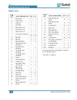
Page 28: ...t 2 2 17 Drive Shaft Seal 1 1 18 O ring Cover 2 2 19 Shur Melt Plug LH Thread 2 2 20 Blank Plug LH Thread 2 2 21 Oil Sight Glass 4 4 22 Pipe Plug 12 12 23 Gear Key 2 2 24 Rotor Shaft Washer 3 3 25 Socket Head Cap Screw 3 3 26 Socket Head Cap Screw 16 16 ITEM NO PART DESCRIPTION STD LS 27 Socket Head Cap Screw 16 16 28 Socket Head Cap Screw 16 16 29 Lock Washer 32 32 30 Dowel Pin 8 8 31 Bearing Shi...

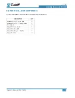
Page 29: ...LATION COMPONENTS These components are recommended for installation and sold separately DESCRIPTION QTY Basic Mounting Kit Driver Side 2 Basic Mounting Kit Passenger Side 2 Port Gasket 2 Blower Port Lock Washer 4 Blower Mounting Bolt 2 Blower Mounting Lock Washer 1 Blower Port Bolt 2 ...

Page 30: ...costs are not included and defective items must be held for Seller s inspection and returned to Seller s Ex works point upon request THEREARE NO WARRANTIES EXPRESSED IMPLIED OR STATUTORY WHICH EXTEND BEYOND THE DESCRIPTION ON THE FACE HEREOF INCLUDING WITHOUT LIMITATION THE IMPLIED WARRANTIES OF MERCHANTABILITY AND FITNESS OF PURPOSE After Buyer s submission of a claim as provided above and its ap...

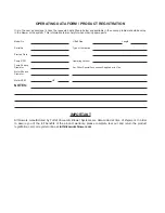
Page 31: ...ze Length Serial No Type of Lubrication Start up Date Pump RPM Operating Vacuum Pump Sheave Diameter Any Other Special Accessories Supplied or in Use Motor Sheave Diameter Motor RPM HP NOTES IMPORTANT All blowers manufactured by Tuthill Vacuum Blower Systems are date coded at time of shipment In order to assure you of the full benefits of the product warranty please complete tear out and return th...

Page 32: ...865 2950 tuthillvacuumblower com Manual 2020 0217 ENG For Service Repair Technical Support or Product Sales contact I N T ERNATIONAL QUALITY STAND A R D REGISTERED VACUUM BLOWER SYSTEMS TUTHILL CORPORATION Copyright 2017 Tuthill Vacuum Blower Systems All rights reserved Product information and specifications subject to change ...

Reviews: