

12
TP9KACX / TP9KSCX
Jan 2017
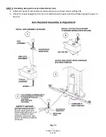
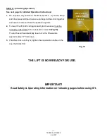
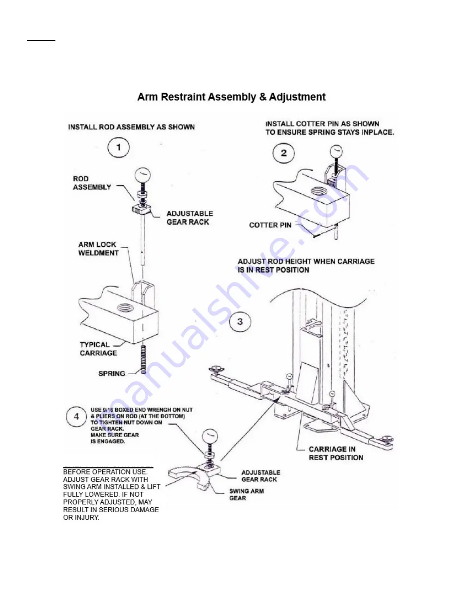
STEP 9: (Installing Swing Arms & Arm Restraints) Cont.
2. Install arm restraint mechanisms to each swing arm, as shown below in (Fig. 13).
3. Check for proper engagement for the arm restraints as the gear rack should fully engage the gear on
the arm.
Fig. 13
SAFETY NOTICE!
Summary of Contents for TP9KACX
Page 4: ...4 TP9KACX TP9KSCX Jan 2017 ...
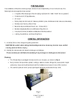
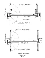
Page 6: ...6 TP9KACX TP9KSCX Jan 2017 Fig 2a TP9KACX Asymmetric Lift Fig 2b TP9KSCX Symmetric Lift ...
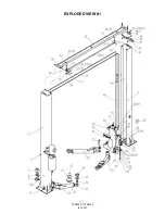
Page 21: ...21 TP9KACX TP9KSCX Jan 2017 EXPLODED VIEW 1 ...
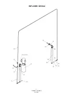
Page 22: ...22 TP9KACX TP9KSCX Jan 2017 EXPLODED VIEW 2 ...
Page 26: ...26 TP9KACX TP9KSCX Jan 2017 ...


