
23
TP9KACX / TP9KSCX
Jan 2017
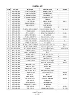
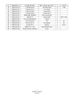
PARTS LIST
ITEM
Tux P/N
M-Ref P/N
DESCRIPTION
QTY
NOTES
1
TP9KACX-001
TT-6835-100-00AKY
Mainside Column
1
2
TP9KACX-002
TT-6835-100-00BKY
Offside Column
1
3
TP9KACX-003
TT-6934-400-10-00KY
High Adaptor 4”
4
4
TP9KACX-004
TT-6934-400-09-00KY
Low Adaptor 1-3/8”
4
5
TP9KACX-005
TT-6835-100-03
Cable Nut
1
6
TP9KACX-006
TT-6934-100-14KY
Adaptor Bracket
2
Q235
7
TP9KACX-007
GB818-85 M8X10
Bolt M8x10
4
8
TP9KACX-008
GB95-1985 D8
Flat Washer D8
4
9
TP9KACX-009
Anchor Bolt
10
10
TP9KACX-010
TT-6835-400-05K-00BMKY
Front / Short Asy. Arm-PS
1
Passenger
11
TP9KACX-011
TPF4-400-04-00
Saddle Pad weldment
2
12
TP9KACX-012
TPF4-400-01A
Rubber Pad, Saddle Pad
2
Rubber
13
TP9KACX-013
GB819-2000 M8X12
Screw M8x12
4
14
TP9KACX-014
TT-6934-046405772
Rubber Pad, Swivel Pad
4
Rubber
15
TP9KACX-015
TT-6934-048417190LKY
Swivel Pad weldment
4
16
TP9KACX-016
TT-6934-048417160KY
Swivel Pad, Screw Collar
4
45
17
TP9KACX-017
GB/T895.2-1986 D28
Circlip D28
4
18
TP9KACX-018
TT-6835-400-05K-00BMKY
Front / Short Asy. Arm-DS
1
Driver
19
TP9KACX-019
TT-6835-400-05-00MKY
Rear / Long Asy, Arm
2
Rear
19A
TP9KACX-019A
TT-6934-400-00MDKY
Sym. Arm (TP9KSCX)
4
TP9KFX/SX
20
TP9KACX-020
TPF4-400-06-00
Swing Arm Pin
4
21
TP9KACX-021
GB70.1-2000 M8X35
Screw
4
22
TP9KACX-022
DL38G-C116A
Rubber Door Guard
2
23
TP9KACX-023
DL38G-C109A
Sliding Rub Block
16
24
TP9KACX-024
TT-6934-200-01-00KY
TP9KX Carriage
2
25
TP9KACX-025
TT-6934-200-02
Plastic Cover, Carriage
4
ABS
26
TP9KACX-026
Pull Knob, Arm Restraint
4
Plastic
27
TP9KACX-027
GB97.2-85 D10
Washer D10
8
28
TP9KACX-028
GB93-87 D10
Washer D10
4
29
TP9KACX-029
GB6170-2000 M10
Nut M10
4
30
TP9KACX-030
TPF4A-200-11-04
改
Gear Bar, Arm Restraint
4
31
TP9KACX-031
TPF4-200-11-05
Plate, Arm Restraint
4
Q235-A
32
TP9KACX-032
qys-200-17
Spring
4
65Mn
33
TP9KACX-033
GB91 d2.5X14
Split Pin D2.5x14
4
34
TP9KACX-034
TPF4A-200-11-01
Rod, Arm Restraint
4
Q235-A
35
TP9KACX-035
TPF4-300-00
Lock Latch
2
36
TP9KACX-036
GB95-1985 D20
Flat Washer D20
2
37
TP9KACX-037
GB818-2000 M6×30
Screw M6x30
2
38
TP9KACX-038
TPF4-300-09
Spring
2
65Mn
39
TP9KACX-039
TPF4-100-12
Plastic Cover, Column
2
PVC 0.007
Summary of Contents for TP9KACX
Page 4: ...4 TP9KACX TP9KSCX Jan 2017 ...
Page 6: ...6 TP9KACX TP9KSCX Jan 2017 Fig 2a TP9KACX Asymmetric Lift Fig 2b TP9KSCX Symmetric Lift ...
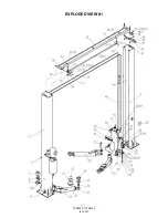
Page 21: ...21 TP9KACX TP9KSCX Jan 2017 EXPLODED VIEW 1 ...
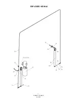
Page 22: ...22 TP9KACX TP9KSCX Jan 2017 EXPLODED VIEW 2 ...
Page 26: ...26 TP9KACX TP9KSCX Jan 2017 ...


