Hangzhou Tuya Inc.
NM1 Module Hardware Design Manual
https://www.tuya.com
Page 22 of 29
4.3.1 RF Antenna Circuit Design
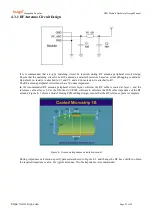
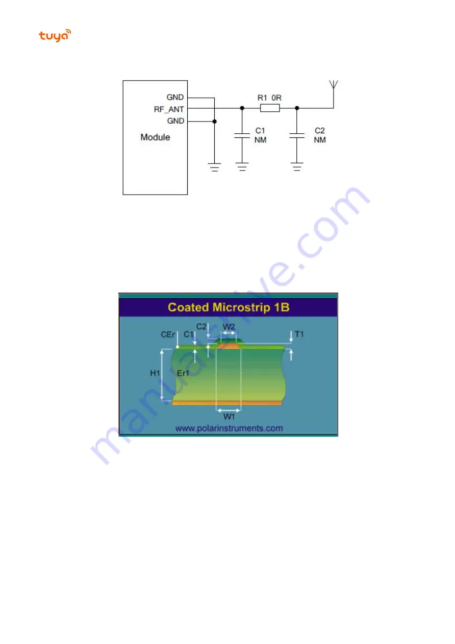
It is recommended that a π-type matching circuit be reserved during RF antenna peripheral circuit design.
Ensure that the matching circuit is near the antenna, and attach resistors based on actual debugging conditions.
By default, no resistor is attached to C1 and C2, and a 0 ohms resistor is attached to R1.
The RF antenna peripheral circuit must have 50 ohms impedance.
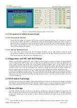
In the recommended RF antenna peripheral circuit layout solution, the RF cable is routed at layer 1 and the
reference cable at layer 2. Use the Shortcut to Si9000 software to calculate the PCB cable impedance of the RF
antenna. Figure 4- 1 shows a model. During PCB cabling design, ensure that the RF reference point is complete.
Figure 4- 1 Antenna impedance calculation model
During impedance calculation, specify parameters shown in Figure 4- 2 and change the RF trace width to obtain
the required impedance value. For typical antennas, 50-ohm impedance is recommended.

