Hangzhou Tuya Inc.
NM1 Module Hardware Design Manual
https://www.tuya.com
Page 16 of 29
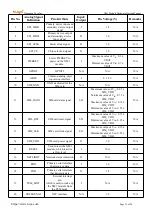
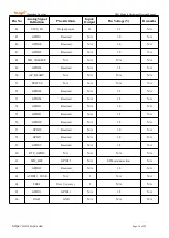
3.4 SIM Card Interface
3.4.1 Pins
Table 3- 4 Definition and description of SIM card interface signals
Pin
No.
Signal Name
Signal Definition
Remarks
11
SIM_DATA
SIM card data pin
Voltage precision: 1.8 V±5%
Maximum current: about 60 mA
13
SIM_CLK
SIM card clock pin
12
SIM_RST
SIM card reset pin
14
SIM_VDD
SIM card power supply pin
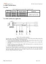
3.4.2 SIM Card Interface Application
Figure 3- 3 SIM card interface application
To ensure a better external SIM card performance and prevent the external SIM card being damaged, design the
SIM card interface circuit in compliance with the following rules:
1. Place the external SIM card holder near the NM1 module. The external SIM card signal cable is 200 mm
or shorter and is away from the RF cable and VBAT power cable.
2. The SIM_VDD decoupling capacitance does not exceed 1 μF, and the capacitor is near the external SIM
card holder.
3. To prevent interference, keep the SIM_CLK and SIM_DATA signal cables at a certain distance from each
other and use a ground cable to separate them.
4. Connect the SIM_RST signal cable to the ground.
To ensure a better ESD performance, you are advised to use TVS tubes to protect the pins of the external SIM
card holder. The parasitic capacitance of the TVS tubes cannot be greater than 50 pF. Place ESD components
near the external SIM card holder. Route the external SIM card signal cable from the external SIM card holder
to the NM1 module through the ESD components.


