Hangzhou Tuya Inc.
NM1 Module Hardware Design Manual
https://www.tuya.com
Page 24 of 29
2. Place the antenna and the coaxial cable that is used to connect the antenna and NIC away from these
interference sources.
3. Place the NM1 module away from components that generate a large amount of heat such as the CPU to prevent
the RF performance being affected by high temperature.
5 Production Instructions
5.1 Stencil Design
During stencil design, note the following:
(1) When making the stencil of the thermal pad at the bottom of the NM1 module, reduce the stencil opening by
25% to reduce short circuits between the thermal pad and functional pins around the NM1 module.
(2) To ensure better soldering, use step stencils.
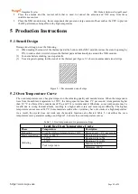
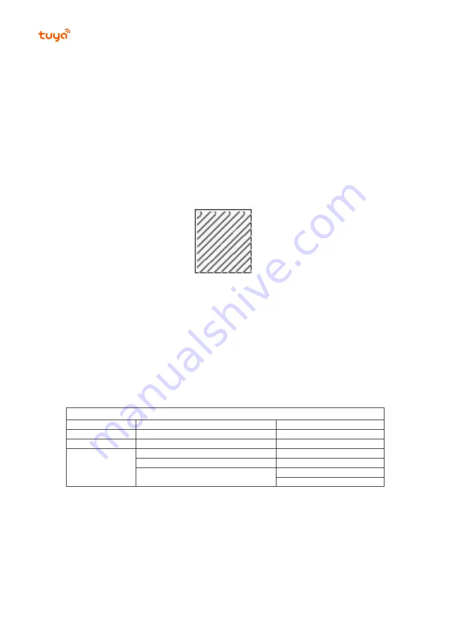
(3) Use a diagonal opening for the stencil of the thermal pad. Figure 5- 1 shows recommended stencil strips.
Figure 5- 1 Recommended stencil strips
5.2 Oven Temperature Curve
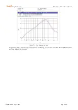
The oven temperature curve has great impact on the soldering quality and material status. When the temperature
rises from the ambient temperature to 150°C, the rising speed is less than 3°C per second. A temperature higher
than 217°C is allowed for a maximum of 70s, and 55s is recommended. Otherwise, some components may be
invalid due to strong thermal attacks, resulting in a higher defect rate and more repair difficulty. The highest
temperature cannot exceed 245°C. Some materials such as the crystal may have die cracks at a high temperature.
As a result, the crystal does not work and the module functions are affected. Table 5- 1 describes the oven
temperature curve parameter settings, and Figure 5- 2 shows the oven temperature curves.
Table 5- 1 Over temperature curve parameter settings
Lead-free Oven Temperature Curve
Phase
Temperature
Description
Preheating
From the ambient temperature to 150°C
Rising speed: < 3°C per second
Heat preservation
150°C to 200°C
Duration: 40s to 110s
Soldering
> 217°C
Duration: 40s to 70s
> 230°C
Duration: 15s to 45s
Peak temperature
Maximum: 245°C
Minimum: 230°C

