background image


TYWRD2S Datasheet 

Hangzhou Tuya Information Technology Co., Ltd.  14 

V2.0.0   

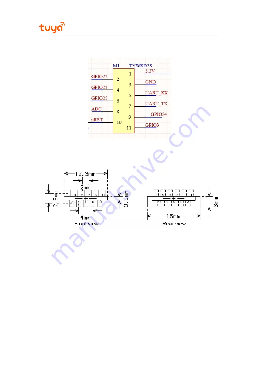
6.2 Recommended PCB Encapsulation 


Figure 6-3 TYWRD2S pins 


Figure 6-4 PCB encapsulation diagram of TYWRD2S 


6.3 Production Instructions 

1.  Use an SMT placement machine to mount components to the stamp hole module that 

Tuya produces within 24 hours after the module is unpacked and the firmware is 

burned. If not, vacuum pack the module again. Bake the module before mounting 

components to the module. 

(1)  SMT placement equipment 

i. 

Reflow soldering machine 

Summary of Contents for TYWRD2S

Page 1: ...can develop embedded Wi Fi products as required 1 1 Features Embedded low power CPU which can also function as an application processor Dominant frequency up to 160 MHz Working voltage 3 0 V to 3 6 V...

Page 2: ...rmation Technology Co Ltd 2 V2 0 0 Working temperature 20 C to 85 C 1 2 Applications Intelligent building Smart household and home appliances Smart socket and light Industrial wireless control Baby mo...

Page 3: ...TYWRD2S Datasheet Hangzhou Tuya Information Technology Co Ltd 3 V2 0 0 Change History No Date Change Description Version After Change 1 2019 07 26 This is the first release 2 0 0...

Page 4: ...8 3 2 Electrical Conditions 9 3 3 TYWRD2S RX Power Consumption 10 3 4 Working Current 10 4 RF Features 10 4 1 Basic RF Features 10 4 2 TYWRD2S Output Power 11 4 3 TYWRD2S RX Sensitivity 11 5 Antenna I...

Page 5: ...13 Figure 6 3 TYWRD2S pins 14 Figure 6 4 PCB encapsulation diagram of TYWRD2S 14 Figure 6 5 HIC for TYWRD2S 15 Tables Table 2 1 TYWRD2S interface pins 6 Table 2 2 TYWRD2S test pins 8 Table 3 1 Absolu...

Page 6: ...x 17 97 0 35 mm Figure 2 1 shows TYWRD2S front and rear views Figure 2 1 TYWRD2S front and rear views 2 2 Interface Pin Definition Table 2 1 TYWRD2S interface pins Pin No Symbol I O Type Function 1 V...

Page 7: ...a standard PWM pin which is connected to GPIO24 pin 32 on the IC 10 RST I O Hardware reset pin active at a low level 11 IO3 I O GPIO_3 a standard PWM pin which is connected to GPIO3 pin 23 on the IC N...

Page 8: ...d corresponding to GPIO2 pin 22 on the IC N A IO8 I O GPIO_8 corresponding to GPIO8 pin 13 on the IC N A IO0 I O GPIO_0 corresponding to GPIO0 pin 36 on the IC Note Test pins cannot be used 3 Electric...

Page 9: ...lectrical conditions Parameter Description Minimum Value Typical Value Maximum Value Unit Ta Working temperature 20 N A 85 C VCC Working voltage 3 0 3 3 3 6 V VIL I O low level input 0 3 N A VCC x 0 2...

Page 10: ...mA 3 4 Working Current Table 3 5 TYWRD2S working current Working Mode Working Status Ta 25 C Average Value Unit EZ The module is in EZ mode 70 mA AP The module is in AP mode 80 mA Connected The modul...

Page 11: ...it Average RF output power 802 11b CCK mode 1 Mbit s N A 17 N A dBm Average RF output power 802 11g OFDM mode 54 Mbit s N A 14 N A dBm Average RF output power 802 11n OFDM mode MCS7 N A 13 N A dBm Fre...

Page 12: ...the Wi Fi module uses an onboard PCB antenna it is recommended that the antenna be at least 15 mm away from other metal parts To prevent adverse impact on the antenna radiation performance avoid coppe...

Page 13: ...echnology Co Ltd 13 V2 0 0 5 3 Antenna Connector Specifications TYWRD2S does not use an antenna connector 6 Packaging Information and Production Instructions 6 1 Mechanical Dimensions Figure 6 1 TYWRD...

Page 14: ...diagram of TYWRD2S 6 3 Production Instructions 1 Use an SMT placement machine to mount components to the stamp hole module that Tuya produces within 24 hours after the module is unpacked and the firmw...

Page 15: ...is lower than 70 2 The shelf life of a dry packaged product is six months from the date when the product is packaged and sealed 3 The package contains a humidity indicator card HIC Figure 6 5 HIC for...

Page 16: ...d severely and dry joints or solder skips may occur Tuya is not liable for such problems and consequences 6 Before SMT placement take electrostatic discharge ESD protective measures 7 To reduce the re...

Page 17: ...Tuya Information Technology Co Ltd 17 V2 0 0 6 5 Storage Conditions 7 MOQ and Packing Information MOQ and packing information Product Model MOQ Packing Method Number of Modules in Each Reel Pack Numbe...

Page 18: ...for a Class B digital device pursuant to part 15 of the FCC Rules These limits are designed to provide reasonable protection against harmful interference in a residential installation This equipment...

Page 19: ...duct must be labeled in a visible area with the following Contains Transmitter Module 2ANDL TYWRD2S This radio module must not be installed to co locate and operating simultaneously with other radios...

Reviews: