background image

4K LCD Monitor  15


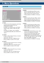
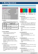
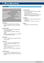
MARKER

- Used to select the marker type when the  

  MARKER is displayed on the screen. 


CENTER MARKER

- Used to select the availability of the    

  CENTER MARKER on the screen.


SAFETY MARKER

- Used to select and control the size and   

  availability of the SAFETY AREA.

- Available types are 80%, 85%, 88%, 90%,  

  93%, 100%, EBU ACTION 16:9, EBU  


  GRAPHIC 16:9, EBU ACTION 14:9, EBU    

  GRAPHIC 14:9, EBU ACTION 4:3 and EBU  

  GRAPHIC 4:3.


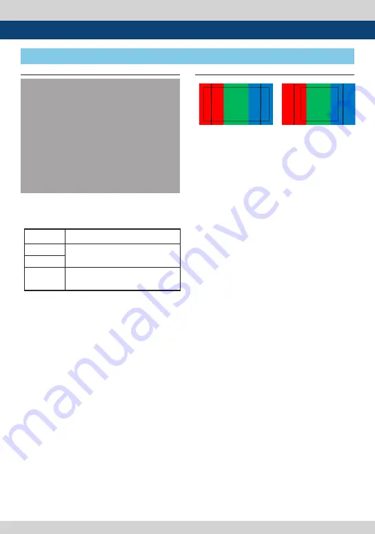
FIT MARKER

- Used to activate or inactivate the FIT    

  MARKER function.

- When the Marker type is selected in the 

  Marker menu, a border line of the Safety  

  Area will be displayed inside the Marker.  

- FIT MARKER ON/OFF displays as shown   

 below.


MARKER MAT

- Used to set the darkness level outside of  

  the MARKER area. 

- Available values are from OFF(transparent)  

  to 7(Black). 


MARKER COLOR

-  Used to control the color of MARKER lines. 

-  Available colors are White, Yellow, Cyan, 

  Green, Magenta, Red, Blue, Black and Adaptive.


THICKNESS

- Used to set the thickness of the MARKER  

 lines. 

- Thickness level is from 1 to 4 by the pixel  

 unit. 


USER MARKER H1

- Used to set the position of the first  


  horizontal marker line.   

- Displayed when MARKER menu is set to  

 USER.


USER MARKER H2

- Used to set the position of the second    

  horizontal marker line.   

- Displayed when MARKER menu is set to  

 USER.


USER MARKER V1

- Used to set the position of the first vertical  

  marker line. 

- Displayed when MARKER menu is set to USER. 


USER MARKER V2

- Used to set the position of the second    

  vertical marker line. 

- Displayed when MARKER menu is set to  

 USER. 

5. Menu Operations

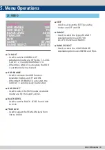
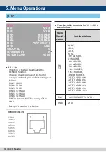
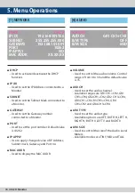
[4] MARKER

MODE

MARKER CLASS

HD

16:9, 4:3, 15:9, 14:9, 13:9, 1.85:1, 

2.35:1, USER

SD 16:9

SD 4:3

16:9, 4:3, 15:9, 14:9, 13:9, 1.85:1, 

2.35:1, USER


MARKER           : 4:3


SAFETY AREA : 90%


FIT MARKER     : OFF


MARKER           : 4:3


SAFETY AREA : 90%


FIT MARKER     : ON

MARKER

CENTER MARKER

SAFETY AREA

FIT MARKER

MARKER MAT

MARKER COLOR

THICKNESS

USER MARKER H1

USER MARKER H2

USER MARKER V1

USER MARKER V2

OFF

OFF

OFF

OFF

OFF

WHITE

1

0

0

0

0

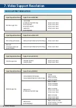
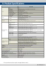
Summary of Contents for LEM-550R

Page 1: ...Multi Format UHD 4K OLED Monitor LEM 550R Operation Manual_v1 0 USB POWER ENTER DOWN UP MENU HDMI MODE SDI...

Page 2: ......

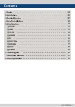
Page 3: ...18 19 20 21 23 Contents 1 Caution 2 MainFeatures 3 Controls Functions 4 MenuTree Adjustment 5 MenuOperations 1 PICTURE 2 VIDEO 3 COLOR 4 MARKER 5 GPI 6 WAVEFORM 7 NETWORK 8 AUDIO 9 SYSTEM 6 FirmwareUp...

Page 4: ...ngerous conditions Request a qualified service person to perform servicing If any of the following conditions occurs unplug the power cord from the DC outlet and request a qualified service person to...

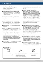
Page 5: ...force and uneven floor surface can cause the product to fall from the cart The vents and other openings in the cabinet are designed for ventilation Do not cover or block these vents and openings since...

Page 6: ...allation in the Studio Wall Wide Screen support This product supports native 16 9 aspect ratio Remote control function This product can simply be Remote controlled by cable connection without addition...

Page 7: ...S 232 AUDIO OUT HDMI IN 12G SDI OUT SDI IN CH 4 SDI IN CH 3 SDI IN CH 2 SDI IN CH 1 USB POWER ENTER DOWN UP MENU HDMI MODE SDI LAN REMOTE RS 422 OUT RS 422 IN RS 232 AUDIO OUT HDMI IN 12G SDI OUT SDI...

Page 8: ...he OSD menu UP Button Used to move up through the menus during the OSD menu activation Also used to increase the value of the selected feature DOWN Button Used to down through the menus during the OSD...

Page 9: ...r HD SD SDI signal The first and second SDI INPUT terminal supports up to 12G input 12G SDI Output BNC 12G signal or BYPASS output terminal for HD SD SDI signal that input through the SDI INPUT termin...

Page 10: ...red menu with the UP DOWN button 3 Press the ENTER button to select a menu and move to a sub menu with the UP DOWN button 4 Press the ENTER button to select the desired sub menu The selected sub menu...

Page 11: ...SAFETY AREA FIT MARKER MARKER MAT MARKER COLOR THICKNESS USER MARKER H1 USER MARKER H2 UAER MARKER V1 USER MARKER V2 GPI GPI 1 GPI 8 GROUP ID MONITOR ID RS 422 BAUD WAVEFORM ENABLE TYPE INTENSITY LINE...

Page 12: ...T Used to control the brightness of the LCD panel backlight from 0 to 127 TIMECODE Used to set the timecode Available modes are OFF and ATC FORCE PSF Force PSF setting The setting mode is ON OFF 4K MO...

Page 13: ...ed to select the HDR modes Available modes are PQ HLG and S LOG3 BLACK LEVEL Used to set the BLACK LEVEL from 0 000 to 0 100 PEAK LUM Used to adjust the PEAK LUM level from 100 to 10000 EETF Used to a...

Page 14: ...n Custom 1 2 3 mode BIAS R Used to set Red Bias or Offset mainly affects on Black level from 128 to 127 Adjusts the red color of dark section Only available in CUSTOM 1 2 3 mode BIAS G Used to set Gre...

Page 15: ...e White Yellow Cyan Green Magenta Red Blue BlackandAdaptive THICKNESS Used to set the thickness of the MARKER lines Thickness level is from 1 to 4 by the pixel unit USER MARKER H1 Used to set the posi...

Page 16: ...unctions for PIN 1 PIN 6 are as follows 5 GPI REMOTE RJ 45 1 Pin1 2 Pin2 3 Pin3 4 Pin4 5 Pin5 6 Pin6 7 Pin7 8 GND 1 8 Menu Classifi cation Settable Values PIN 1 6 NONE SDI A SDI B HDMI 16 9 MARKER 4 3...

Page 17: ...he WAVEFORM type Available modes are OFF WAVEFORM VECTORSCOPE and WAVE_VECTOR INTENSITY Controls the brightness of the WAVEFORM display Available values are between 1 63 LINE WAVEFORM Used to display...

Page 18: ...sed to control the audio volume Control range is from 0 to 30 and the default value is 15 AUD CH Used to set the audio channel Available ranges are GR1 CH1 CH2 GR1 CH3 CH4 GR2 CH1 CH2 GR2 CH3 CH4 GR3...

Page 19: ...Y PASS mode the selected channel s image is output as it is In 12G signal output signal is changed to 12G OSD DISPLAY Used to set the OSD MENU DISPLAY time Available modes are CONTINUE 3 SEC and 20 SE...

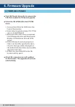
Page 20: ...is completed the S W upgrade starts and the progress displays on the bottom left side of the screen 4 If the USB doesn t connect properly or there is no file in the specified location the error messa...

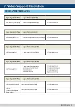
Page 21: ...ignal Interfaces Signal Format 3G_A SDI 3G SDI single link 1920x1080 50 59 94 60p YCbCr 4 2 2 10bit Input Signal Interfaces Signal Format 3G_B SDI 3G SDI single link 1920x1080 50 59 94 60p 23 98 24 25...

Page 22: ...Quad link 4k 3840x2160 23 98 24 25 29 97 30p YCbCr 4 2 2 10bit Input Signal Interfaces Signal Format SD SDI SD SDI single link 720x487 59 94i 720x576 50i YCbCr 4 2 2 10bit YCbCr 4 2 2 10bit Input Sig...

Page 23: ...50p 3G SDI LEVEL A 1920x1080 60i 59 94i 50i 30p 29 97p 25p 24p 23 98p 3G SDI LEVEL B 1280x720 60p 59 94p 50p 3G SDI LEVEL B SMPTE 274M 1920x1080 60i 59 94i 50i 30p 29 97p 25p 24p 23 98p SMPTE 296M 128...

Page 24: ...02 345 4 8 12 FOR MORE INFORMATION PLEASE VISIT http www tvlogic tv 12F ACE HIGH END 8 84 Gasan digital 1 ro Geumcheon gu Seoul 18590 KOREA TEL 82 70 8668 6611 FAX 82 2 6123 3201 E mail sales tvlogic...

Reviews: